


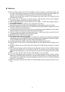
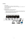
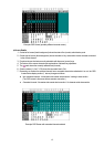
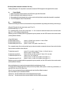
Example OSD Screen (probably different to actual screen)
a) Screen Details
1. Center-left of screen (black background) shows the state of the (master) switch device ports.
2. Center-right of screen (blue background) shows the state of any slave switch device cascade connected
to the current channel.
3. Purple text shows the hosts currently selectable with the arrow (cursor) keys.
4. The bottom of the screen shows simple explanations of allowed key operations.
5. The mark shows the currently selected host (channel).
6. Green numbers (1~8 or F1~F8) show the connected host is ON.
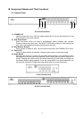
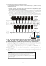
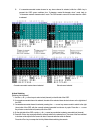
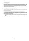
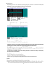
7. Depending on whether the selected channel has a cascaded slave device attached to it or not, the OSD
master device display section (1. above) changes as follows:
● Non-cascaded channel: 14-character wide master device section / nothing in slave section.
(The OSD screen is the same without cascade connection.)
● Cascaded channel: 3-character wide master device section / 14-character wide slave section.
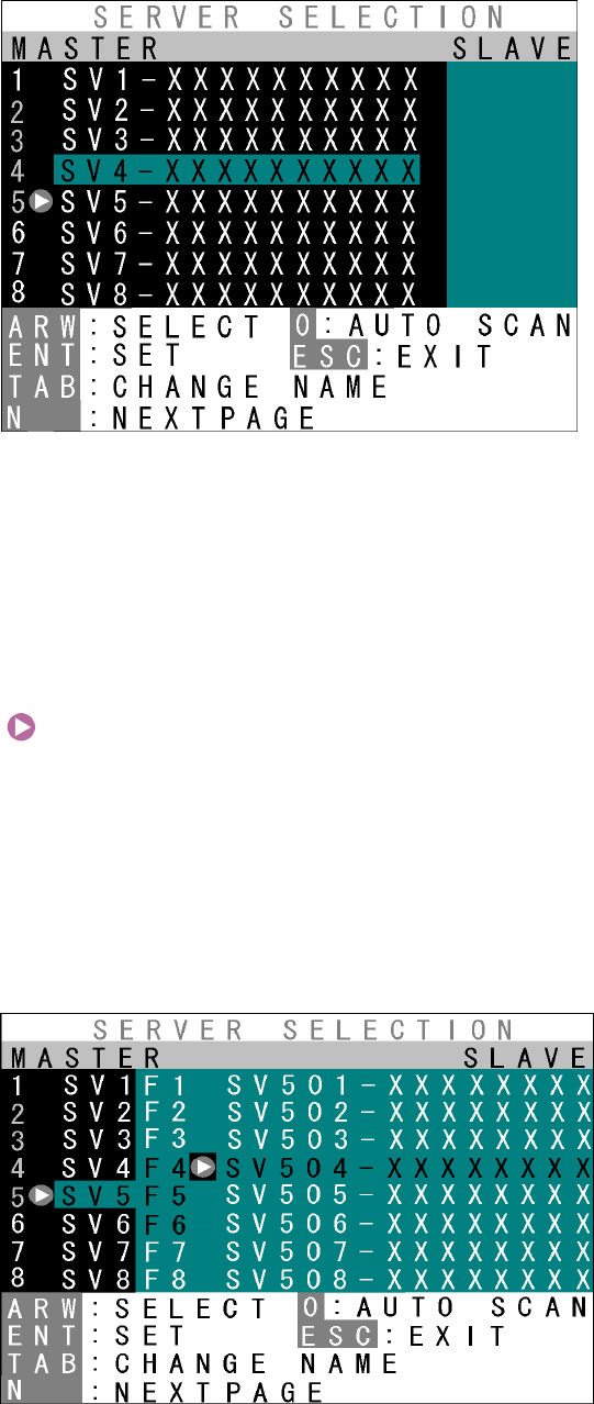
Example OSD Screen with cascaded channel selected
13