IN-2 C141-E064-03EN
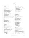
External operator panel 4-28, 4-29
External operator panel circuit example 4-29
External operator panel connector 4-18, 4-19
External operator panel connector signals
4-20
F
FG 4-29
FORMAT UNIT command 5-17
Format capacity 3-10
Format parameter 5-17
Function specifications 2-2
G
G list 3-12
G1 3-8
Gaps 3-8
General description 1-1
General notes 5-1
H
Hardware function test 6-2
Head configuration 1-8
Heads 1-8
High speed data transfer 1-2
High speed positioning 1-4
Humidity 2-4
I
Indicating revision number 6-7
Initial self-diagnostics 6-2
Input signal 4-20
Installation 5-1, 5-2
Installation requirements 4-1
Interface connector 4-17
Interface test 6-5
Internal test space 3-4
L
LBA 3-8
LUN 1-11
Large capacity 1-4
Leak magnetic flux 4-11
Limitation of side-mounting 4-9
Location of connector A-2, A-3
Logical data block addressing 3-11
Low noise 1-5
Low power consumption 1-5
Low vibration 1-5
M
MODE SELECT EXTENDED command 5-
18
MODE SELECT command 5-18
MR 1-8
MTBF 2-5
MTTR 2-5
Magnet - Resistive 1-8
Maintenance information 6-5
Maintenance requirements 6-5
Microprocessing unit 1-9
Mode setting 5-8
Mode settings 5-9
Model name 2-1, D-1, D-2
Motor start mode 5-8
Motor start mode setting 5-8
Mounting drives 5-10
Mounting frame structure 4-8
Mounting orientation 4-8
Mounting procedure 5-10
Mounting requirements 4-1
N
Noise filter 4-15
Notes on mounting 4-8
O
Online self-diagnostics 6-3
Outer view 1-5, 1-6, 1-7
Output signal 4-21
Output signal for external LED 4-22
P
PAD 1 3-9
PAD 2 3-9
PAD 3 3-9
PLO sync 3-8
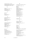
EPR4ML 1-9
Packaging 5-2
Partial response class 4 maximum likelihood
1-9
Parts that can be replaced in the field 6-6
Physical sector allocation 3-6
Positioning error rate 2-5
Power cable 4-28
Power on/off sequence 4-13, 4-14
Power requirements 2-4, 4-13
Power supply 4-17
Power supply connector 4-17, 4-25
Prefetches 1-3
Preparating after Installation for use 5-12
Preventive maintenance 6-5


