


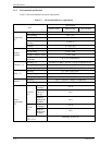

1.2 Hardware Structure
C141-E237 1-5
1.2 Hardware Structure
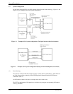
The HDDs have a disk enclosure (DE) and a printed circuit assembly (PCA). The DE includes heads
on an actuator and disks on a spindle motor mounted on the DE. The PCA includes a read/write
circuit and a controller circuit.
(1) Disks
The disks have an outer diameter of 70 mm (2.8 inch) and an inner diameter of 25 mm (0.98 inch).
The disks are good for at least 50,000 contact starts and stops.
(2) Heads
The MR (Magnet – Resistive) of the CSS (contact start/stop) type heads are in contact with the disks
when the disks are not rotating, and automatically float when the rotation is started.
(3) Spindle motor
The disks are rotated by a direct-drive hall-less DC motor. The motor speed is controlled by a
feedback circuit using the counter electromotive current to precisely maintain the specified speed.
(4) Actuator
The actuator, which uses a rotary voice coil motor (VCM), consumes little power and generates little
heat. The heads at the end of the actuator arm are controlled and positioned via feedback servo loop.
The heads are positioned on the CCS zone over the disks when the power is off or the spindle motor
is stopped.
(5) Read/write circuit
The read/write circuit utilizes a read channel mounted with a head IC that supports high-speed
transmission and an MEEPR4ML (Modified Enhanced Extended Partial Response Class 4 Maximum
Likelihood) modulation/demodulation circuit in order to prevent errors being triggered by external
noise and to improve data reliability.
(6) Controller circuit
The controller circuit uses LSIs to increase the reliability and uses a high speed microprocessing unit
(MPU) to increase the performance of the SAS controller.