


Installation Requirements
4-10 C141-E237
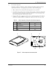
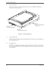
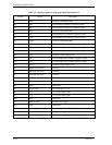
Table 4.2 Interface connector (SAS plug) signal allocation:CN1
Pin No. Signal Description
S1 GND GND for SAS Primary Port
S2 RP+ SAS Primary Port Receive (positive) signal
S3 RP- SAS Primary Port Receive (negative) signal
S4 GND GND for SAS Primary Port
S5 TP- SAS Primary Port Transmit (negative) signal
S6 TP+ SAS Primary Port Transmit (positive) signal
S7 GND GND for SAS Primary Port
S8 GND GND for SAS Secondary Port
S9 RS+ SAS Secondary Port Receive (positive) signal
S10 RS- SAS Secondary Port Receive (negative) signal
S11 GND GND for SAS Secondary Port
S12 TS- SAS Secondary Port Transmit (negative) signal
S13 TS+ SAS Secondary Port Transmit (positive) signal
S14 GND GND for SAS Secondary Port
P1
Note1
Reserved (not used) Not used
P2
Note1
Reserved (not used) Not used
P3
Note1
Reserved (not used) Not used
P4 GND GROUND
P5 GND GROUND
P6 GND GROUND
P7 +5V-Charge Pre-charge pin for +5V
P8 +5V +5V power supply input
P9 +5V +5V power supply input
P10 GND GROUND
P11 READY LED READY LED output
P12 GND GROUND
P13 +12V-Charge Pre-charge pin for +12V
P14 +12V +12V power supply input
P15 +12V +12V power supply input
Note 1) P1 to P3 are 3.3V power supply input and pre-charge signals, and not used on MAXxxxxRC.