


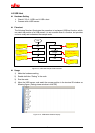
Usage
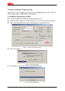
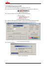
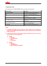
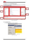
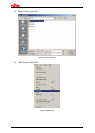
1) Open Nand Flash sample project, and start debug.
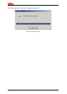
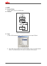
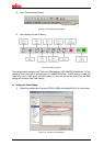
2) Use “step over” to debug, and watch local variable “sec”, “min”, “hour”.
4.4 CAN
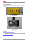
Hardware Setting
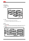
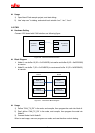
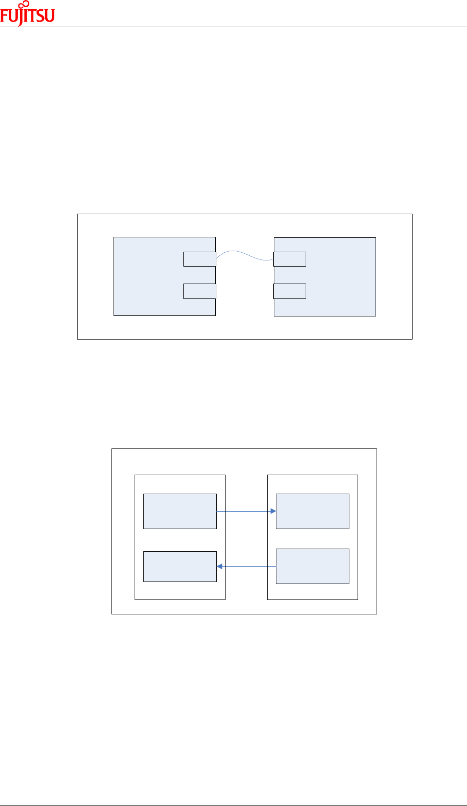
Connect 2 EV-board with CAN interface, as following figure.
CAN 1
CAN 2
CAN 1
CAN 2
EV board 1
(Node A)
EV board 2
(Node B)
Figure 4-6: CAN Hardware Connection
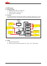
Block Diagram
¾ Node A: use buffer 10 (ID = 0x12345678) to transfer and buffer 8 (ID = 0x08765432)
to receive
¾ Node B: use buffer 7 (ID = 0x12345678) to receive and buffer 10 (ID = 0x08765432)
to transfer.
Buffer 10
(ID=0x12345678)
Buffer 8
(ID=0x08765432)
Buffer 7
(ID=0x12345678)
Buffer 10
(ID=0x08765432)
Node A Node B
Figure 4-7: CAN Demo Block Diagram
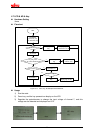
Usage
1) Define “CAN_TX_RX” in the code, and compile, then program the code into Node A
2) Don’t define “CAN_TX_RX” in the code, and compile, then program the code into
Node B.
3) Connect Node A with Node B
When in real usage, user can program one node, and use the other node to debug.
17