


3.1 Environmental Requirements
C156-E228-02EN 3-3
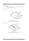
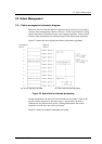
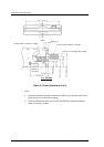
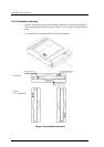
3) Cut off part of the wall surrounding the optical disk (disk outer wall) as
shown in Figure 3.1.
At this point, cut off a section 5 to 10 mm in width from the disk outer wall.
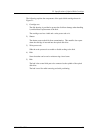
4) Using an adhesive agent, affix the tip of the thermocouple to the opening of
the disk outer wall.
5) Pass the thermocouple through the hole in the cartridge and reassemble the
cartridge.
Using an adhesive agent, etc., fill any gap between the hole and the
thermocouple.
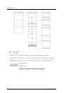
Note: The surface of the cartridge shown in Figure 3.1 has been cut away to
illustrate the elements inside the cartridge. Do not actually cut away the
surface.
If the external environment temperature rises above the specified value,
the drive will take protective action to deal with the temperature increase
by automatically placing an interval between commands before
responding to a command.
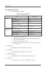
3.1.3 Temperature rise
Table 3.2 Temperatures at measuring points (Reference)
[Ambient temperature of the optical disk drive: 45°C]
Measurement point Random seek Criteria
Inside cartridge 53°C 55°C
IC (controller) surface
73°C 85°C
IC (read Amp.) surface
75°C 85°C
Thermal sensor 51°C
−
Notes:
1. The above data was taken in a constant temperature chamber in which the
temperature around the optical disk drive was kept at 45°C. The data was not
taken with the drive installed in a box in which the drive is actually used.
2. Note that, when installed in a box, the ambient temperature around the drive
will differ depending on the air circulation conditions of the box, and the
temperature increase inside the cartridge will differ accordingly.