


C141-E099-01EN6 - 8
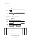
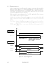
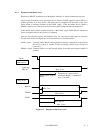
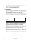
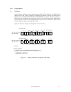
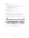
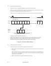
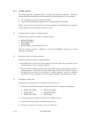
(2) LBA mode
Logical address assignment in the LBA mode starts from physical cylinder 0, physical head 0,
and physical sector 1. The logical address is advanced at the subsequent sector from the last
sector of the current track. The first physical sector of the subsequent physical track is the
consecutive logical sector from the last sector of the current physical track.
Figure 6.6 shows an example of (assuming there is no track skew).
LBA
2
LBA
1
SPSPLBA
405
406405
LBA
404
LBA
0
321
Physical sector
ex: Zone 0
Physical parameter
- Physical sector: 1 to 406 (For the rest, 2 spare sectors)
Physical cylinder 0
Physical head 0
......................
......................
SPSPLBA
811
LBA
810
321
Physical cylinder 0
Physical head 1
......................
......................
LBA
408
LBA
407
LBA
406
408407
406405 408407
Figure 6.6 Address translation (example in LBA mode)
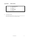
6.3 Power Save
The host can change the power consumption state of the device by issuing a power command
to the device.
6.3.1 Power save mode
There are four types of power consumption state of the device including active mode where all
circuits are active.
In the power save mode, power supplying to the part of the circuit is turned off. There are
three types of power save modes:
• Idle mode
• Standby mode
• Sleep mode
(1) Active mode
In this mode, all the electric circuit in the device are active or the device is under seek, read or
write operation.