


C141-E099-01EN5 - 34
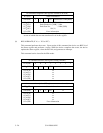
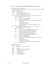
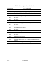
Table 5.5 Information to be read by IDENTIFY DEVICE command (5 of 5)
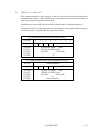
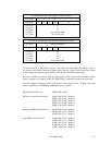
*20 Word 93: CBLID– detection results
Hardware reset result. The contents of bits 12-0 of this word shall change only during the
execution of a hardware reset.
Bit 15: Shall be cleared to zero
Bit 14: Shall be set to one
Bit 13: 1=Device detected CBLID– above V
IH
0=Device detected CBLID– below V
IL
Bit 12-8: Device 1 hardware reset result. Device 0 shall clear these bits to zero
Device 1 shall set these bits as follows:
Bit 12: Reserved
Bit 11: 0=Device 1 did not assert PDIAG–
1=Device 1 asserted PDIAG–
Bit 10-9: These bits indicate how Device 1 determined the device number:
00=Reserved
01=a jumper was used
10=the CSEL signal was used
11=some other method was used or the method is unknown
Bit 8: Shall be set to one
Bit 7-0: Device 0 hardware reset result. Device 1 shall clear these bits to zero
Device 0 shall set these bits as follows:
Bit 7: Reserved
Bit 6: 0=Device 0 does not respond when Device 1 is selected
1=Device 0 responds when Device 1 is selected.
Bit 5: 0=Device 0 did not detect the assertion of DASP–
1=Device 0 detected the assertion of DASP–
Bit 4: 0=Device 0 did not detect the assertion of PDIAG–
1=Device 0 detected the assertion of PDIAG–
Bit 3: 0=Device 0 failed diagnostics
1=Device 0 passed diagnostics
Bit 2-1: These bits indicate how Device 0 determined the device number:
00=Reserved
01=a jumper was used
10=the CSEL signal was used
11=some other method was used or the method is unknown
Bit 0: Shall be set to one
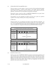
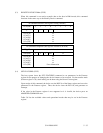
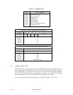
*21 Word 128: Security status
Bit 15-9: Reserved
Bit 8: Security level 0=High, 1=Maximum
Bit 7-6: Reserved
Bit 5: 1=Enhanced security erase supported
Bit 4: 1=Security count expired
Bit 3: 1=Security frozen
Bit 2: 1=Security locked
Bit 1: 1=Security enabled
Bit 0: 1=Security supported