


C141-E112-01EN
5 - 88
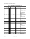
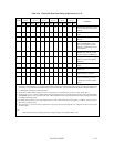
i) The CRC generator polynomial is : G (X) = X16 + X12 + X5 + 1.
Note: Since no bit clock is available, the recommended approach for calculating CRC is to
use a word clock derived from the bus strobe. The combinational logic shall then be
equivalent to shifting sixteen bits serially through the generator polynomial where DD0 is
shifted in first and DD15 is shifted in last.
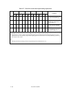
5.5.6 Series termination required for Ultra DMA
Series termination resistors are required at both the host and the device for operation in any of the
Ultra DMA Modes. The following table describes recommended values for series termination at
the host and the device.
Table 5.15 Recommended series termination for Ultra DMA
Signal Host Termination Device Termination
DIOR-:HDMARDY-:HSTROBE 22 ohm 82 ohm
DIOW-:STOP 22 ohm 82 ohm
CS0-, CS1- 33 ohm 82 ohm
DA0, DA1, DA2 33 ohm 82 ohm
DMACK- 22 ohm 82 ohm
DD15 through DD0 33 ohm 33 ohm
DMARQ 82 ohm 22 ohm
INTRQ 82 ohm 22 ohm
IORDY:DDMARDY-:DSTROBE 82 ohm 22 ohm
RESET- 33 ohm 82 ohm
Note: Only those signals requiring termination are listed in this table. If a signal is
not listed, series termination is not required for operation in an Ultra DMA Mode.
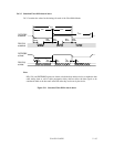
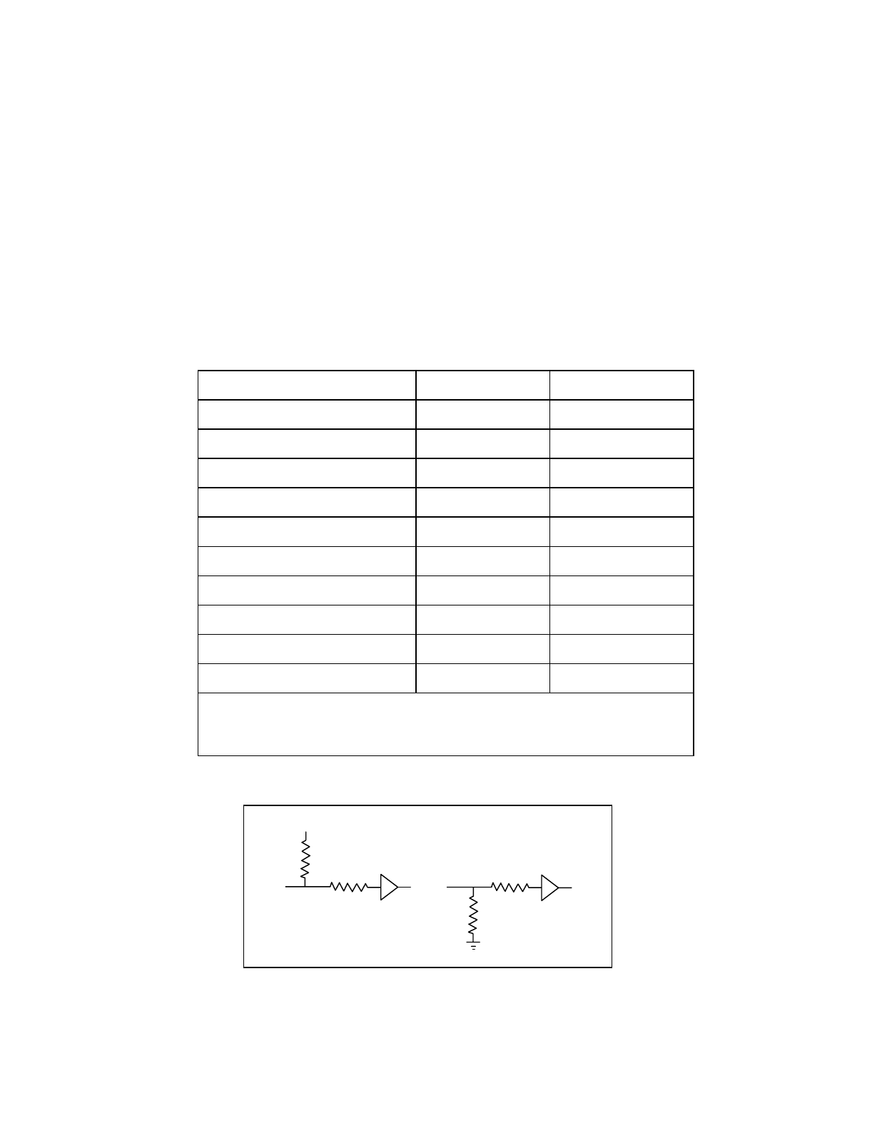
For signals also requiring a pull-up or pull-down resistor at the host see Figure 5.7.
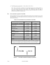
Figure 5.7 Ultra DMA termination with pull-up or pull-down
Vcc