


C141-E112-01EN
4 - 13
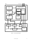
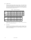
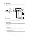
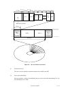
4.7.1 Servo control circuit
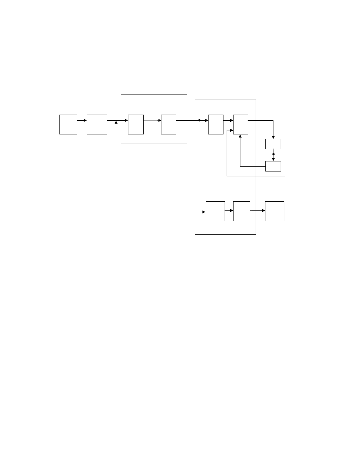
Figure 4.4 is the block diagram of the servo control circuit. The following describes the functions
of the blocks:
(5)
(1)
(2) (3) (4)
P.
Amp.
CSR: Current Sense Resistor
VCM: Voice Coil Motor
Spindle
motor
control
DSP
unit
Servo
burst
capture
SVC
MPU
CSR
Driver
DACADC
Position Sense
Head
VCM current
VCM
Spindle
motor
(7)(6)
Figure 4.4 Block diagram of servo control circuit
(1) Microprocessor unit (MPU)
The MPU includes DSP unit, etc., and the MPU starts the spindle motor, moves the heads to the
reference cylinders, seeks the specified cylinder, and executes calibration according to the internal
operations of the MPU.
The major internal operations are listed below.
a. Spindle motor start
Starts the spindle motor and accelerates it to normal speed when power is applied.
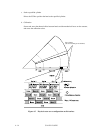
b. Move head to reference cylinder
Drives the VCM to position the head at the any cylinder in the data area. The logical initial
cylinder is at the outermost circumference (cylinder 0).