


C141-E112-01EN 5 - 93
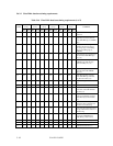
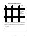
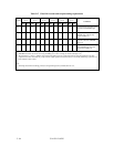
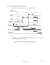
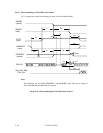
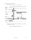
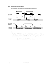
Table 5.16 Ultra DMA data burst timing requirements (2 of 2)
MODE 0
(in ns)
MODE 1
(in ns)
MODE 2
(in ns)
MODE 3
(in ns)
MODE 4
(in ns)
MODE 5
(in ns)
NAME
MIN MAX MIN MAX MIN MAX MIN MAX MIN MAX MIN MAX
COMMENT
t
AZ
10 10 10 10 10 10 Maximum time allowed for output
drivers to release (from asserted or
negated)
t
ZAH
20 20 20 20 20 20 Minimum delay time required for
output
t
ZAD
0 0 0 0 0 0 Drivers to assert or negate (from
released)
t
ENV
20 70 20 70 20 70 20 55 20 55 20 50 Envelope time (from DMACK- to
STOP and HDMARDY- during
data in burst initiation and from
DMACK to STOP during data out
burst initiation)
t
RFS
75 70 60 60 60 50 Ready-to-final-STROBE time (no
STROBE edges shall be sent this
long after negation of DMARDY-)
t
RP
160 125 100 100 100 85 Ready-to-pause time (that recipient
shall wait to pause after negating
DMARDY-)
t
IORDYZ
20 20 20 20 20 20 Maximum time before releasing
IORDY
t
ZIORDY
0 0 0 0 0 0 Minimum time before driving
IORDY (*4)
t
ACK
20 20 20 20 20 20 Setup and hold times for DMACK-
(before assertion or negation)
t
SS
50 50 50 50 50 50 Time from STROBE edge to
negation of DMARQ or assertion
of STOP (when sender terminates
a burst)
*1: Except for some instances of t
MLI
that apply to host signals only, the parameters t
UI,
t
MLI
and t
LI
indicate sender-to-recipient or
recipient-to-sender interlocks, i.e., one agent (either sender or recipient) is waiting for the other agent to respond with a signal before
proceeding. t
UI
is an unlimited interlock that has no maximum time value. t
MLI
is a limited time-out that has a defined minimum. t
LI
is a limited time-out that has a defined maximum.
*2: 80-conductor cabling shall be required in order to meet setup (t
DS
, t
CS
) and hold (t
DH
, t
CH
) times in modes greater than 2.
*3: Timing for t
DVS
, t
DVH
, t
CVS
and t
CVH
shall be met for lumped capacitive loads of 15 and 40 pf at the connector where all signals (Data
and STROBE) have the same capacitive load value. Due to reflections on the cable, the measurement of these timings is not valid in
a normally functioning system.
*4: For all modes the parameter t
ZIORDY
may be greater than t
ENV
due to the fact that the host has a pull up on IORDY- giving it a known
state when not actively driven.
*5: The parameters t
DS
, and t
DH
for mode 5 is defined for a recipient at the end of the cable only in a configuration with one device at the
end of the cable.
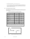
Note:
All timing measurement switching points (low to high and high to low) shall be taken at 1.5V.