


SECTION 2
2.1
ISOLATED REMOTE ANALOG
INTERFACE OPERATION
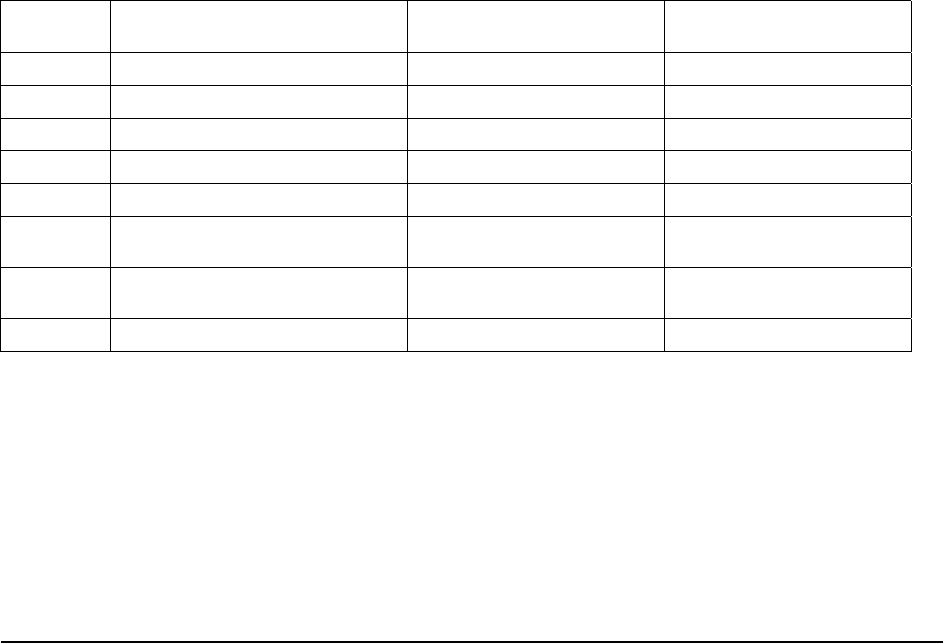
INTFC SETUP Switch
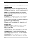
The INTFC SETUP (Interface Setup) switch is accessible from the rear panel of the unit. It
provides user selectability of the programming/monitoring ranges and signal types, as well as
configuring the power supply for operation under remote control. Setting a switch to the UP
position enables a function. The factory default settings are all switch positions OFF (down).
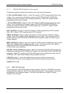
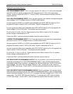
See Figure 2–1 for a rear panel view of low-voltage models DLM5–75M51A, DLM 8–75M51A,
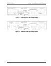
DLM 20–30M51A, DLM 40–15M51A, and DLM 60–10M51A. Refer to Figure 2–2 for a rear
panel view of high-voltage models DLM 80–7.5M51A, DLM 150–4M51A, and DLM 300–2M51A.
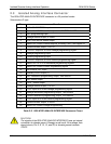
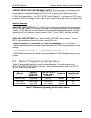
Switch
Position
Function OFF (Down) Position ON (Up) Position
1 V, 10V or 4-20mA Select 0-5VDC 0-10VDC or 4-20mA
2 I, 10V or 4-20mA Select 0-5VDC 0-10VDC or 4-20mA
3 OVP, 10V Select 0-5VDC 0-10VDC
4 VMON, 10V Select 0-5VDC or 4-20mA 0-10VDC
5 IMON, 10V Select 0-5VDC or 4-20mA 0-10VDC
6
EXT-OFF, Active-Low
Select
Active-High Logic Level Active-Low Logic Level
7 LCK-OUT
Enable Front Panel
Controls
Lockout Front Panel
8 Not Used — —
Table 2–1. INTFC SETUP Switch
M51A Option 2-1