


DLM 600W Series Isolated Remote Analog Interface Operation
M51A Option 2-9
4. Program the other parameters to the desired limit values: VOLTAGE PROGRAMMING
INPUT, Pin-9, and the CURRENT PROGRAMMING INPUT, Pin-10, with respect to
Pin-12.
5. Connect Pin-1, ANALOG-CONTROL, of the ISOLATED ANALOG INTERFACE
connector to Pin-15.
2.4.4
2.4.5
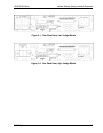
Resistance Programming of Output Voltage
Setting up for resistance programming of the output voltage is as follows:
1. Set Position-1, V, of the INTFC SETUP switch to OFF (down) for 0-5VDC programming
range.
2. Connect the external programming resistance, 0-5kΩ, to the ISOLATED ANALOG
INTERFACE connector, from Pin-21 to Pin-12.
3. Connect a jumper from Pin-21 to Pin-9.
4. Program the other parameters to the desired limit values: CURRENT PROGRAMMING
INPUT, Pin-10, and the OVP PROGRAMMING INPUT, Pin-3, with respect to Pin-12.
5. Connect Pin-1, ANALOG-CONTROL, of the ISOLATED ANALOG INTERFACE
connector to Pin-15.
Resistance Programming of Output Current
Setting up for resistance programming of the output current is as follows:
1. Set Position-2, I, of the INTFC SETUP switch to OFF (down) for 0-5VDC programming
range.
2. Connect the external programming resistance, 0-5kΩ, to the ISOLATED ANALOG
INTERFACE connector, from Pin-22 to Pin-12.
3. Connect a jumper from Pin-22 to Pin-10.
4. Program the other parameters to the desired limit values: VOLTAGE PROGRAMMING
INPUT, Pin-9, and the OVP PROGRAMMING INPUT, Pin-3, with respect to Pin-12.
5. Connect Pin-1, ANALOG-CONTROL, of the ISOLATED ANALOG INTERFACE
connector to Pin-15.