


Isolated Remote Analog Interface Operation DLM 600W Series
2-2 M51A Option
2.1.1
2.2
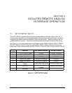
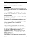
INTFC SETUP Switch Functions
The following sections describe the functions of the various switch positions:
V, 10V or 4-20mA Select: Position-1, when ON, selects 0-10VDC programming of the output
voltage. Also, must be set to ON position when the ISOLATED ANALOG INTERFACE
connector is wired for 4-20mA output voltage programming. When OFF, selects 0-5VDC
programming of the output voltage.
I, 10V or 4-20mA Select: Position-2, when ON, selects 0-10VDC programming of the output
current. Also, must be set to ON position when the ISOLATED ANALOG INTERFACE
connector is wired for 4-20mA output current programming. When OFF, selects 0-5VDC
programming of the output current.
OVP, 10V Select: Position-3, when ON, selects 0-10VDC programming of OVP threshold.
When OFF, selects 0-5VDC programming of OVP threshold.
VMON, 10V Select: Position-4, when ON, selects 0-10VDC range for readback of output
voltage. When OFF, selects 0-5VDC readback of output voltage. Also, must be set to OFF
position when the ISOLATED ANALOG INTERFACE connector is wired for 4-20mA output
voltage readback.
IMON, 10V Select: Position-5, when ON, selects 0-10VDC range for readback of output current.
When OFF, selects 0-5VDC readback of output current. Also, must be set to OFF position
when the ISOLATED ANALOG INTERFACE connector is wired for
4-20mA output current readback.
EXT-OFF, Active-Low Select: Position-6, when ON, selects the ACTIVE-LOW logic level for
disabling the output with the EXTERNAL-OFF signal of the ISOLATED ANALOG INTERFACE
connector. When OFF, selects the ACTIVE-HIGH logic level for disabling the output with the
EXTERNAL-OFF signal of the Isolated Analog Interface connector.
LCK-OUT: Position-7, when ON, disables the front panel controls; the front panel
LOCAL(REMOTE) switch will not toggle between the front panel and remote control.
Position-8: Not used
SETUP Switch
Only two positions of the SETUP switch remain functional: Position-1, REM SNS, for remote
sensing selection; Position-2, SLAVE, for master/slave selection. Their operation is the same
as presented in the Operation Manual. The other switch positions, Position-3 through
Position-8, are not used.