


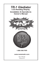
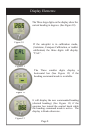

Installation of Basic LCD Display
Installation Overview:
• Figure out where on your dash you want to mount the display, or
optional mounting panel. Be sure to allow plenty of room in the
back of the display for mounting accessibility.
• You will need good visibility and convenient reach of the
display.
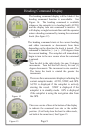
• Cut a 3-3/4” hole in the desired location.
• Mount the display using the mounting hardware provided.
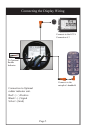
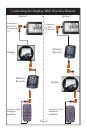
• Make the proper wire connections to the ECU, the Handheld and
to the rudder reference indicator (optional).
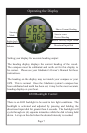
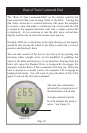
• Turn the Gladiator autopilot system on with the deckmount
On/Off switch and verify display connections. The display should
momentarily light up all functions of the display, then show all
OOO’s across the heading display and STBY will blink for 30
seconds and then display STBY as the mode selection.
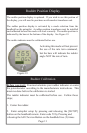
• If the Rudder Position Indicator Transducer is used, it must be
installed and calibrated before this mode will work correctly. See
pages 11 & 12 of this manual.
Tools required:
Electric Drill
3.725 dia. hole saw
5/16” open end wrench
Safety Glasses
Additional tools for Mounting Optional Panel:
File for making additional clearances
.75 dia. hole saw
.156 or 5/32” drill bit
Page 3