


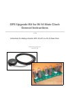

How To Connect The GPS
Furious activity is no substitute for understanding. -H. H. Williams
These instructions assume that you are adding the GPS upgrade to a completed IN-14
nixie clock kit purchased through tubeclock.com. If you are adding the upgrade at the
same time as building the kit, you will not need to remove the standard parts. Simply
substitute the parts that came with the GPS upgrade kit instead. If you purchased a
completed IN-14 nixie clock, you may use these instructions to upgrade the clock
yourself.
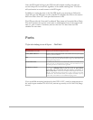
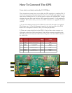
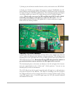
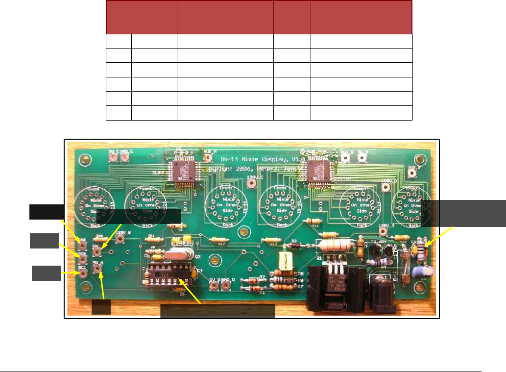
1) To provide sufficient current for the GPS unit, resistor R1 will need to be replaced.
This resistor was a ½ Watt 1k Ohm part, located on the right hand side of the PCB.
Remove R1 and replace it with the 1 Watt, 100 Ohm part provided.
2) There are six wires which lead to the GPS-18. Each of these wires connects to a
solder pad on the Nixie Clock circuit board. Snip off the connector provided on the
GPS-18, strip the wire ends, and solder them to the pads on the clock PCB as listed in
the table below.
GPS
18
Pin #
Color Signal Name Wire
Gauge
Connection Point on
Clock
1 Yellow Pulse Per Second Output 28 RA0
2 Red V
in
– 5V Power In 26 5V_A
3 Black Ground 28 GND_A
4 White GPS Serial Transmit 28 RC1
5 Black Ground 26 GND_A
6 Green GPS Serial Receive 28 RC0
Yellow
Green
White
Red
Replace Microcontroller
Replace R1
with 100Ohm 1W
Yellow
Black (two wires)