


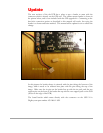
Update
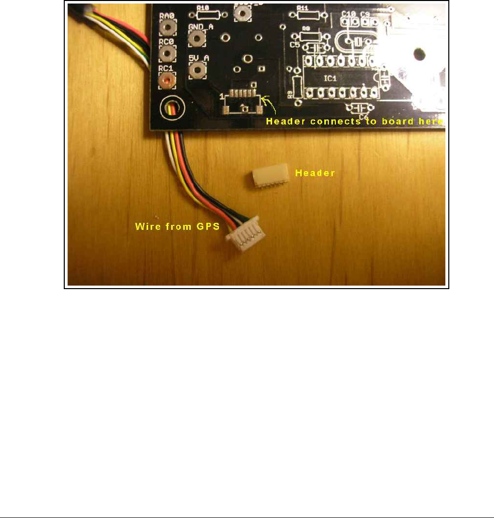
The new revision of the the PCB has a place to put a header to mate with the
connector which is already on the GPS unit. The surface mount header is shown in
the picture below, and is now included with the GPS upgrade kit. Connecting to the
thru-hole connection points as described in this manual still works, but using the
header is a cleaner and easier method. This manual will be updated soon to reflect this
change.
In this picture the header shown is oriented with the pins facing the bottom of the
image, while it needs to be soldered into place with the pins facing the top of the
image. Make sure the six pins on the header line up with the six pads, and the two
support pins on the front of the header line up with the two support pads on the PCB
(closest to the edge of the PCB).
The board header which mates directly with the connector on the GPS 18 is
Digikey.com part number 455-1806-1-ND.