


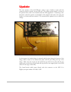
3) Gently pry the old microcontroller from the socket, and insert the new PIC16F688.
4) Finally, the 12V DC power adapter will need to be replaced. WARNING: the 12V
power adapter which shipped with the non-GPS kit is transformer based, and provides
too high a Voltage for the GPS modified clock. The transformer based power adapter
can actually output up to about 18V, which will burn out the 100Ohm dropping
resistor. Please make sure to use the GPS modified clock ONLY with a switch-
mode 12V power adapter, a 12V battery, or other true 12V source. The 12V
power adapter included with the GPS upgrade kit is a switch-mode power supply
which will work without problems.
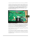
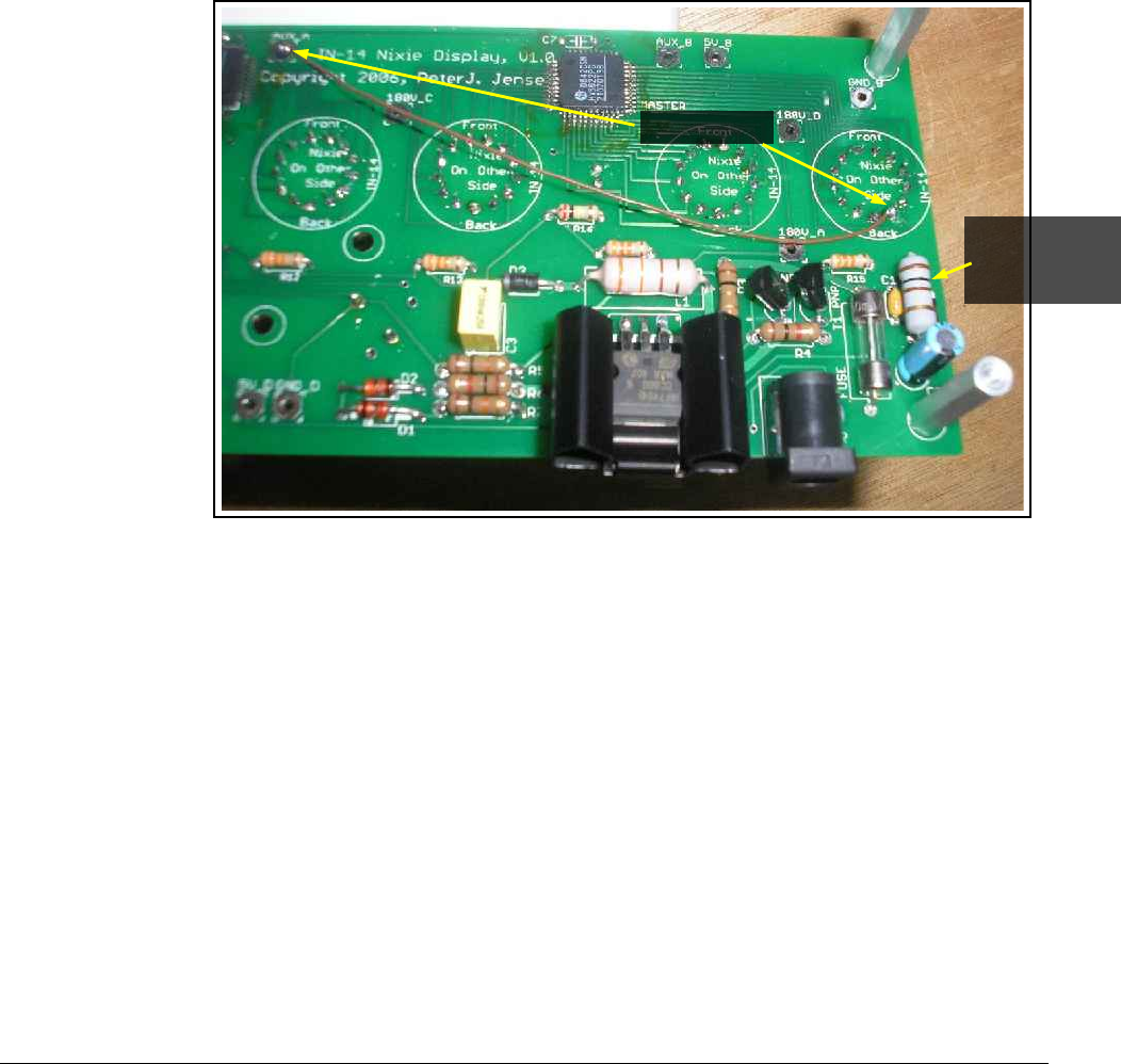
Optional PPS Active Indicator
5) Optionally, although recommended, you may wish to run a jumper wire from the
AUX_A pad to the decimal point indicator on the seconds nixie. This will light up the
decimal point on the right hand nixie as long as PPS signal has been received from the
GPS within the last second. Remember that the GPS takes about five minutes to
get synchronization on power-up before the PPS signal will be received.
The decimal point pins on the nixies are directly to the left and right of the bottom-
most pin- approximately in the 5 o'clock and 7 o'clock positions. You can use any
decimal point you wish as the indicator.
The AUX_B pad can also be used, except this pad will toggle on or off each time a
new pulse is received on the PPS line. The effect of connecting to the AUX_B pad is
the indicator will turn on for a second, then off for a second, and then repeat so long
as the PPS signal is active. If the PPS signal stops, the AUX_B connected indicator
will maintain it's last state.
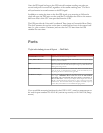
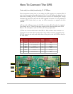
Jumper Wire
New 100Ohm,
1Watt
Resistor R1