


Magnum 4K8 Switches Installation and User Guide (10/04)
6
www GarrettCom com
..
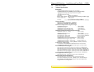
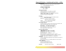
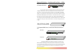
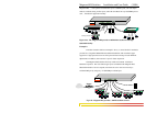
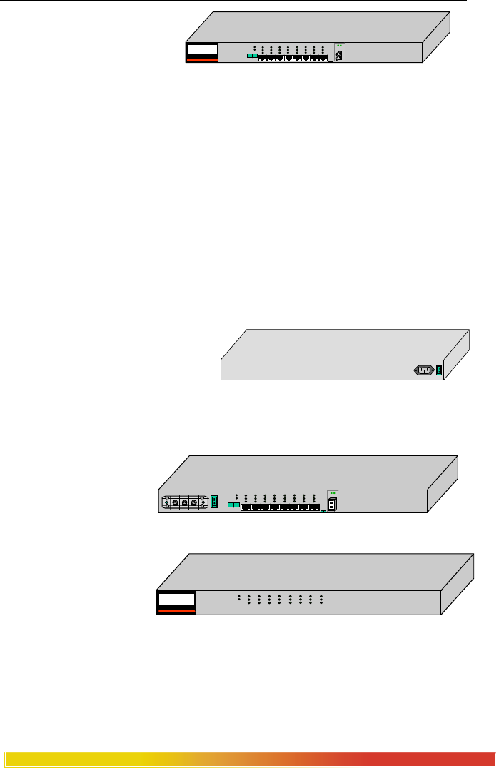
Figure 2.2.1a: Front view, 8-
port Magnum 4K8 Switches
All port, LED’ connector and manual switches are located on the front panel
of Magnum 4K8 Switches. There are power(PWR) and error(Error) indicators for the
unit. There are Link and Activity(Link/Act) indicators for each 10Mbps and 100Mbps
domain, for visual indication of the operating status of each domain, and there are Soeed
and F/H Full and Half duplex Leds for each port. The manual switch with (=, x)supports
the port#1 for crossover port feature, whereas “F-H” manual switch for FPM port are
user selectable for full fixed and half duplex. The IEC standard AC power connector (and
a manual ON - OFF power switch) located at the rear. Fan-driven cooling air flows left
to right.
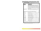
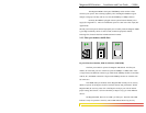
Figure 2.2.1b: Rear view - Magnum
table-top & rack-mount 4K8 Switch
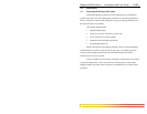
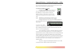
2.2.2: Magnum 4K8R “Reverse” model, front LEDs and connections in
rear
Rear View
Front View
The Magnum 4K8R is like the 4K8F except that the front panel has the
LEDs, and all the connecting ports and power feeds are in the back. This is convenient
for rack-mounting where cabling is accessed from the rear of the rack while the operating
status LEDs are monitored from the front. Typically such arrangements are found in
Telco rack installations.
1 2 3 4 5 6 7 8
A L
POWER
ERROR
L/A
SPEED
F/H
MAGNUM 4K-Series
Ethernet 10/10 0 Switch
UPLINK
= X
F
H
ON
OFF
110-220
VAC
47-63Hz
1.0-0.5A
1 2 3 4 5 6 7 8
A L
POWER
ERROR
L/A
SPEED
F/H
UPLINK
= X
F
H
(-) GND (+)
48V DC
ON
OFF
F
H
1 2 3 4 5 6 7 8
POWER
ERROR
L/A
SPEED
F/H
MAGNUM 4K8
Ethernet 10/100 Switch