


Magnum 4K8 Switches Installation and User Guide (10/04)
17
www GarrettCom com
..
MAGNUM 4K-Series
Ethernet 10/100 Switch
1 2 3 4 5 6 7 8
POWER
ERROR
L/
SPEE
F/H
UPLINK
= X
A L
F
H
F
H
MAGNUM 4K-Series
Ethernet 10/100 Switch
1 2 3 4 5 6 7 8
POWER
ERROR
L/
SPEE
F/H
UPLINK
= X
A L
F
H
F
H
MAGNUM 4K-Series
Ethernet 10/100 Switch
1 2 3 4 5 6 7 8
POWER
ERROR
L/
SPEE
F/H
UPLINK
= X
A L
F
H
F
H
MAGNUM 4K-Series
Ethernet 10/100 Switch
1 2 3 4 5 6 7 8
POWER
ERROR
L/
SPEE
F/H
UPLINK
= X
A L
F
H
F
H
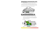
2. Connect the other end of the cable to the corresponding device
3. Use the LINK LED to ensure proper connectivity by noting that the LED will be
illuminated when the unit is powered and proper connection is established.
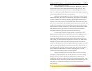
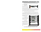
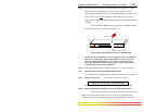
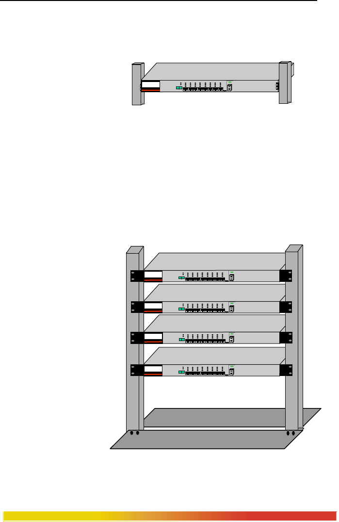
3.3 Rack-mounting
Installation of a
Magnum 4K8 Switch in a 19”
rack is a simple procedure. The
units are 1U (1.70”) high. When
properly installed, the front-mounted LED status indicators should be in plain view and
easy to read. Rack-mount installation requires special 19” rack-mounted brackets and
screws (included with each 4K8 unit). The brackets attach to the front sides of the
Switch, which is then fastened into a standard 19” RETMA rack.
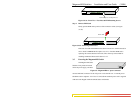
The 23” brackets and ETSI brackets are also available (optional) for rack-
mounting of Magnum 4K Series Switches. The 23” brackets are popular in the Telco
industry where they are a standard for Central Office rack mounting purposes. The 23”
brackets are mainly being used for larger equipment assemblies in rack-mounting frames,
and are frequently accessed in
operation from both sides.
The ETSI (European
Telephone Standard) brackets
are similar to the 19” brackets
but use metric dimensions.
The optional 23”
brackets and the ETSI brackets
come as a pair in a package,
along with the necessary screws
for attaching the brackets to the
sides of the Magnum Switch
unit.
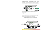
Fig 3.3 Multiple Magnum 4K8 units rack-mounted in a 23” frame
MAGNUM 4K-Series
Ethernet 10/100 Switch
1 2 3 4 5 6 7 8
POWER
ERROR
L/A
SPEED
F/H
UPLINK
= X
A L
F
H
F
H