


Magnum 4K8 Switches Installation and User Guide (10/04)
21
www GarrettCom com
..
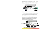
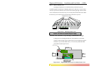
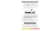
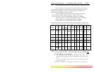
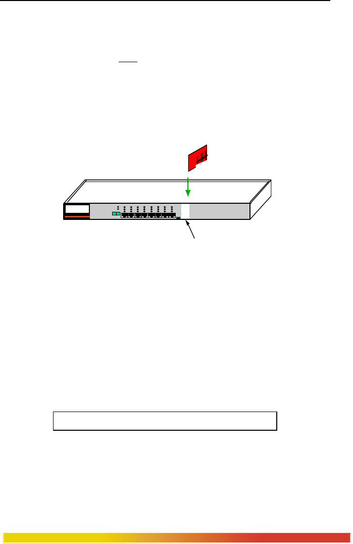
Step 3. Be sure the pins are precisely aligned with the holes in the header, and the
FPM front panel is guided into the front slot cut-out. Then, slowly and
carefully apply enough pressure to insert the FPM card pins into position, see
Figure 3.4.2b. (If you force
the FPM down when the pins are not properly
aligned with the holes in the header, the pins will become bent and the FPM is
damaged).
Once inserted, the FPM card will be secured by the header connector,
the front panel port slot cut-out, and retaining screws.
Figure 3.4.2b: Inserting PM Cards into a Magnum 4K8
NOTE: The optional FPM slots need not be filled in order for the Magnum
4K8 unit to be operational. When leaving FPM slots empty, always use a
face plate (Magnum FPM-BLNK) to cover the slot opening in the front
panel. This will maintain proper cooling air flow, safety, and operation as
required by FCC, CE, and other regulations.
Step 4. Once FPM cards have been installed, the chassis cover should be replaced.
3.4.3 Removing FPM Cards from Magnum 4K8 Switches
To properly remove an FPM card from a 4K8 Switch, follow the 3 steps below.
Step 1. Remove chassis cover See procedure in Section 3.4.1 above.
Caution: Be sure the power cord is unplugged.
Attention: Soyez sûr que le cordon de secteur est débranché
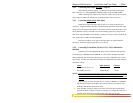
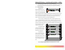
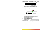
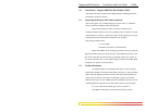
Step 2. Remove bottom-front retaining screw for the FPM and Face Plate
On the bottom-front of the unit there is one retaining screws for each
FPM card and face plate slot. These screws are used to secure a FPM card in
position (see Figure 3.4.3a). Remove the front screw of the FPM to be removed.
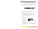
FPM CARD
FPM Empty slot ready for installation
MAGNUM 4K-Series
Ethernet 10/100 Switch
1 2 3 4 5 6 7 8
POWER
ERROR
L/A
SPEED
F/H
UPLINK
= X
F
H