


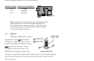
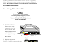
3. Connect the Transmit (TX) port (light colored post) on the Magnum RPM-FST to
the Receive (RX) port of the remote device. Begin with the color-coded strand of
the cable for this first TX-to-RX connection.
4. Connect the Receive (RX) port (dark colored post) on the RPM-FST to the
Transmit (TX) port of the remote device. Use the non-color coded fiber strand for
this.
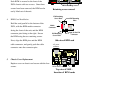
5. The LINK LED on the front of the RPM-FST will illuminate when a proper
connection has been established at both ends (and when power is ON in the unit).
If LINK is not lit after cable connection, the normal cause is improper cable
polarity. Swap the fiber cables at the Port Module connector to remedy this
situation.
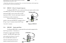
3.3.6 Connecting Fiber Optic (SC-type, "Snap-on")
The same five-step procedure as for fiber ST-type applies to FOIRL and
10BASE-FL applications using an RPM-FSC card used with SC-type fiber connectors.
Follow the five steps as described in the paragraph above.
When connecting fiber media to SC connectors, simply snap on the square male
connector into the female SC jack of the device until it clicks and secures.
3.3.7 Connecting Single-Mode Fiber Optic (SMF)
When using the RPM-SMF, be sure to use single-mode fiber cable. Single-mode
fiber cable has a smaller diameter than multi-mode Fiber cable (2/15 - 8/60 microns for
single-mode, 50/125 or 62.5/125 microns for multi-mode where xx/xx are the diameters of the
core and the core plus the cladding respectively). Because of this, single-mode fiber allows
full bandwidth at longer distances, and may be used to connect nodes up to 10 Km apart.
The same five-step procedure for multi-mode fiber ST-type applies to single-