


Magnum 6KM Mobile Ethernet Switch Installation and User Guide 07/10
36
www GarrettCom com
..
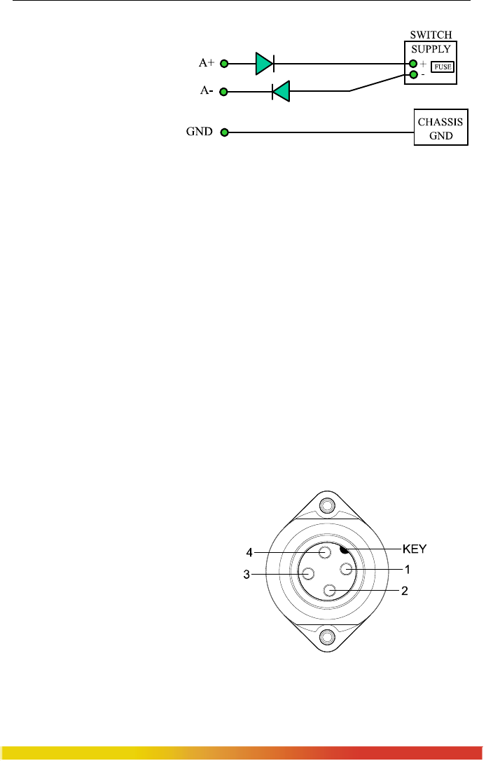
B2.0 12, 24, –48, 110, 125 and 250VDC POWER, THEORY OF OPERATION
The 12, 24, -
48VDC, 110, 125 and
250VDC power options are
designed using diodes inside
on each DC power input line
behind the two external
power connection terminals,
so that the power from an
external source can only
flow into the hub. This allows the Switch to operate only whenever DC power is
correctly applied to the two inputs. It protects the Switch from incorrect DC input
connections. An incorrect polarity connection, for example, will neither affect the
Switch, its internal power supply, nor will it blow the fuse in the internal power supply.
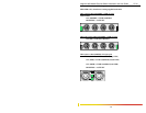
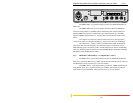
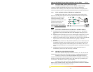
B3.0 6KM DC SINGLE SOURCE INSTALLATION
This section describes the proper connection of the 12, 24, –48, 110, 125 and
250VDC to the DC power connector on the Magnum 6KM Switch. The DC input
connector on the Magnum 6KM Mobile Switch is located on the left front of the unit.
The power terminals are connected as shown below, and they are electrically floating
inside the unit so that either may be grounded by the user if desired. The chassis is
“earth” or ground (GND).
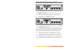
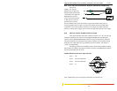
The mating connection to the 6KM switch is made utilizing a RD24, locking,
female connector. Simply align the keyed female connector to the 6KM male connector
and twist the threaded lock to secure.
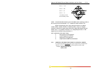
Standard 6KM male DC Power Input connector:
Pin 1= A
+
Pin 2= NC (Not connected)
Pin 3= NC (Not connected)
Pin 4= A
-
Note: for Dual-Source power input pins specification, see Section C5.0