g
GE
OPM_SGS_USM_10K_40K_0US_V010.doc 13/88 Operating Manual
SG Series
10, 20, 30 & 40 kVA
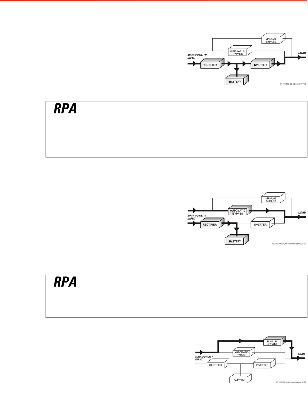
3.2.3 Utility recovery operation
As soon as the AC input power recovers, the
Rectifier will start automatically,
supplying DC
power to the Inverter and recharging the Battery.
If the Inverter was previously shut down due to low
Battery, the Load will be initially powered by Utility
through the
Automatic Bypass
.
When the Battery is recharged enough to ensure a
minimum time of operation with the present load,
the Inverter will start automatically and the Load
will be transferred back to the Inverter.
Fig. 3.2.3-1 Block diagram Utility recovery operation
In case of parallel operation
When the AC input power recovers, the Rectifiers will start up sequentially, according to their
number in the parallel system. This minimizes the
initial inrush current.
The Inverters will start up automatically, but only when the Battery has recharged enough for
a
minimum runtime
with the present load.
When enough Inverters to supply the Load have been restarted, the Load will be transferred
from the Automatic Bypass back to the Inverter output.
3.2.4 Automatic Bypass
In normal operation, the Load is supplied by the
Inverter.
When the control system detects a fault in the
Inverter, an overload condition or a short-circuit
condition, the Automatic Bypass will transfer the
critical Load to the Utility without interruption.
When the Inverter recovers, or the overload or
short-circuit condition is corrected, the Load will be
automatically transferred back to the Inverter.
If the UPS is unable to return to normal mode
following an automatic transfer to Bypass mode, an
alarm condition will be initiated.
A Manual Bypass (operator initiated) will not be
considered as an alarm condition.
FIG. 3.2.4-1 BLOCK DIAGRAM AUTOMATIC
BYPASS
In case of parallel operation
Each unit has it’s own internal Bypass. These units are continuously exchanging information,
enabling all of the internal Bypass circuits in a parallel system to operate simultaneously.
If the Inverter of a unit fails, it’s Bypass circuit remains available to the parallel system.
It is excluded only if the unit is separated from the common bus by opening it’s output switch Q1.
3.2.5 Manual Bypass
The Manual Bypass circuit consists of
Q1
and
Q2
manual switches, which permits transfer of the
Load directly to the unconditioned AC power
without interruption, leaving the UPS available for
maintenance.
Fig. 3.2.5-1 Block diagram Manual Bypass


