


2
DEH40206 Installation Instructions
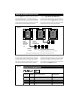
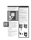
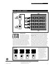
The dataline connects relay panels, softwired switches and
optional control modules. Within the 4-wire dataline are two
twisted pairs: the red and black wires, carrying data; and the
blue and white wires, providing power to the dataline switches.
For simplicity, we refer to a 4-wire dataline running between
a relay panel and the dataline switches as a “Local Dataline”.
The relay panel provides the low-voltage power to all of the
dataline switches on its local dataline.
Note: To ensure good communications between panels,
the installer must comply with the dataline specification.
GE will not warrant a system using a dataline that does
not meet our specification. To avoid questions, use
GE RLONWIRE-4P (plenum rated). Do not run the
dataline in conduit or wiring trays with power wires.
Do not connect the local datalines from two different
panels.
GE RLONWIRE-4P Dataline Wire Specifications
• #18 AWG (7 strands x 26 AWG)
• 2 independent twisted pairs – black/red, blue/white
• Unshielded copper conductors
• 2 inch twist lay on pairs, 6 inch twist lay on cable
• Plenum-rated copolymer jacket, 0.230" O.D.
• FEP 0.010" insulation, 0.060" O.D.
• 30 pF/foot maximum capacitance
• -20°C to 150°C operating temperature range
• 17 lbs. per 500 foot reel
• UL rated
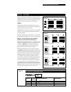
If you have purchased the ProSys Lighting Control System (the
stand-alone system), the devices (panels, switches and clock)
will be in self-install mode. This means that as soon as they
are connected to the network, they are operational and can
communicate with each other.
If you have purchased the ProSys LM Lighting Control System
along with the ProSys LM software, the devices will be in
software-install mode. This means that you must use your
network management tool to:
¥
assign network addresses to the devices and
¥
bind network variables and message tags.
Addresses and binding are necessary for the devices to
function on the network. ProSys LM users please refer to the
ProSys LM Software User Guide for instructions on installng
devices.
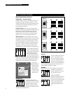
This instruction sheet will show you how to:
1. Install and Test a Local Dataline
2. Install and Test Dataline Switches
3. Softwire a Dataline Switch to Control a Group of Relays or
a Channel within a Single Panel
4. Document the Softwiring
LOCAL DATALINE INSTALLATION