


6
DEH40206 Installation Instructions
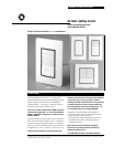
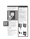
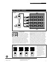
SWITCH BUTTON LABELING
The individual switch buttons provide space for
3
⁄8" wide x 1
1
⁄16"
long (9mm x 30mm) label directories. The directory labels can
be attached simply by removing the clear lenses, positioning
the labels and replacing the lenses as shown at right.
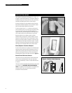
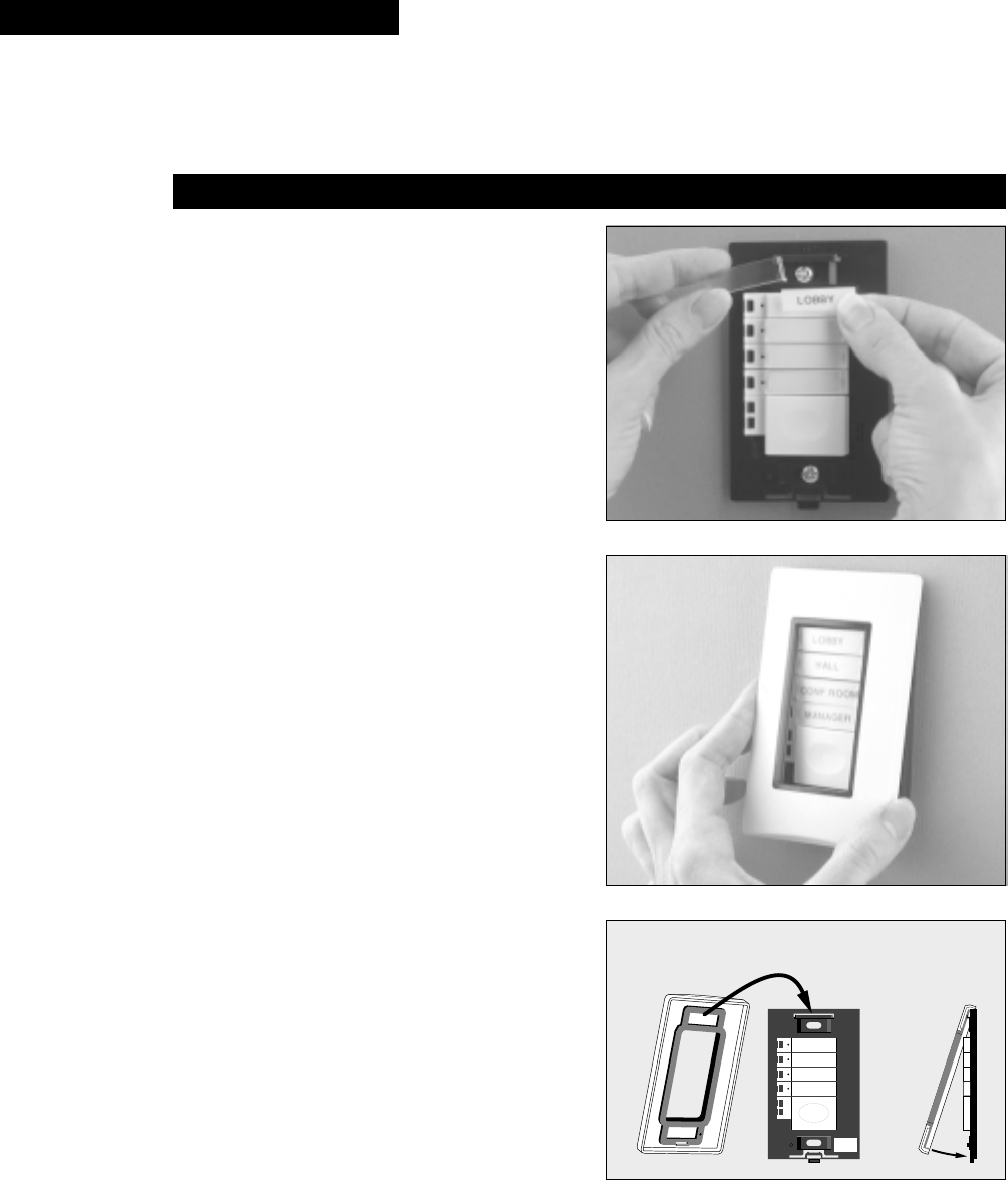
If desired, the buttons may be completely removed from the
base plate and labeled separately. You may find this method
easier to achieve better alignment of the labels.
To remove a button from a 1-, 2- or 4-button switch, open it
out from the base until it is at a 90° angle, then gently rotate
it up or down until it snaps free of the hinge bracket. To
replace the button, press the hinge pin into the hinge bracket
until it snaps in place, then close the button into position.
Removing buttons from an 8-button switch is slightly
different. With your fingernail or small screwdriver, pry the
hinge end of the button free from the hinge bracket. Lift the
button out, twisting it slightly, if necessary, to free the small
hook holding the center edge of the button in place. To replace
the button, position the small center hook in place and press
the hinge pin into the hinge bracket until it snaps in place.
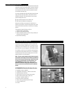
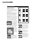
Remove/Replace Screwless Wallplate
To remove the screwless cover plate, press in the black tab at
the bottom edge of the plate and lift the plate up and off. To
replace the cover plate, place the hang bar at the top of the
plate onto the hang hook at the top of the switch base and
snap the bottom in place until it clicks as shown in Figure 4.
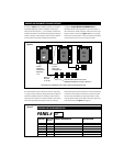
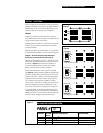
Record Switch Reference Numbers
The switch’s reference number (Panel #-Switch #) should be
written on the small label placed in the lower right hand
corner of the switch base, so that it is visible when the cover
is removed.
The relays or channel associated with each button of the switch
are recorded on the DATALINE SWITCH DOCUMENTA-
TION form supplied with the relay panel. The completed form
should be stored in the cover of the relay panel that is
connected to this local dataline.
Panel#
Switch#
01
02
Figure 4 – Dataline Switch Numbering