


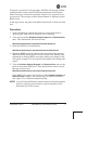
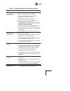

MENU SYSTEM
Flowchart
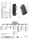
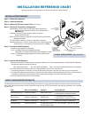
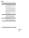
CONNECTORS AND INDICATORS
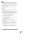
LED FUNCTIONS & INDICATIONS
LAN......ON............LAN detected
Flashing....Data TX/RX
OFF ..........LAN not detected
COM1...Flashing....Data TX/RX Activity
OFF ..........No data activity
GPS ...ON ............Has satellite fix
Flashing....Synchronizing
OFF ..........No satellite fix
Standard Unit
Option Set 1
Remote
Insert to P/N 05-4458A01
GE MDS
175 Science Parkway
Rochester, NY 14620 USA
www.GEmds.com
Ntwk. Intfc. Config
Ethernet Port Config
Bridge Configuration
SNMP Agent Config. (AP)
AP Location Info (RM)
SNTP Server Config.
Network
Configuration
Radio
Configuration
Device
Information
Maintenance/Tools
Security
Configuration
Reprogramming
Config. Scripts
Ping Utility
Auth. Codes
Reset to Defaults
Radio Test
F/W Versions
F/W Upgrade
MAIN MENU
Network Name
Transmit Power
Receive Pwr. (AP)
Freq. Control
Adv. Config.
Performance
Information
NOTES
• Chart shows top-level view only. See Reference Manual for details.
• Not all menu items are-user configurable
Serial Number
Uptime
Date
Date Format
Time
Model
Device Names
Console Bd. Rt.
UTC Time Offset
Device Security
Wireless Security
Event Log
Packet Statistics
GPS Status
Wireless Ntwk Stat.
Intl. Radio Stat. (RM)
Performance Trend
Manage Certif.
RADIUS
Configuration
Starting Information Screen
(Read-Only Status)
Redundancy
Configuration (AP)
Redundancy Config.
Ntwk Event Triggers
Radio Event Triggers
Hdwr Event Triggers
Red. Config. Options
Force Switchover
GPS
Configuration (RM)
Stream GPS to Console
Send GPS via UDP
GPS UDP Server IP Address
GPS UDP Server UDP Port
PWR.....ON............Primary power (DC) present
Flashing....Alarm present
OFF ..........Primary power (DC) absent
Access Point
Remote Gateway
LINK .....ON............Default state
Flashing....Data Tx/Rx
LINK .....ON............Associated to AP
Flashing....Data Tx/Rx
OFF ..........Not Associated with AP
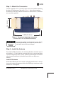
COM1
SERIAL PORT
LAN PORTS
GPS ANTENNA
CONNECTION
RX2 ANTENNA
PORT
TX/RX1
ANTENNA PORT
DC POWER INPUT
(10—30 VDC, 2.5A)
LED INDICATOR
PANEL
WiFi ANTENNA
PORT
USB PORTS
(Mini-A, Type-A)
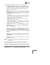
• Spacebar is used to make some menu selections
• AP = Access Point Only
• RM = Remote Only
COM1
SERIAL PORT
LAN PORT
GPS ANTENNA
CONNECTION
RX2 ANTENNA
PORT
TX/RX1
ANTENNA PORT
DC POWER INPUT
(10—30 VDC, 2.5A)
LED INDICATOR
PANEL