


PB3-POS-RP ProBridge
User Manual
16
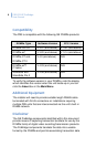
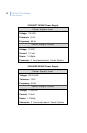
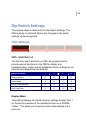
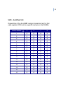
Switch Settings as shown above are:
• Camera Number 1 (SW1 5-8)
• Generic Printer (SW3 1-8)
• PB3 Termination OFF (SW4 3)
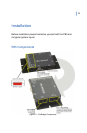
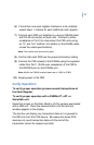
Detailed Installation Steps
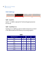
Note: Modify the DVMRe’s default baud rate of 19200 to 57600.
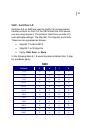
1) At the minimum set or verify the DIP Switch settings for the
Camera Number, PB3 Termination, and the type of serial
device.
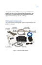
2) Disconnect the existing serial device cable from the Printer
and install the ECR Interconnect Cable (multiple DB25
connectors) to the serial device as shown on page 14.
Note: If the existing connection is using a DB9 to DB9 connection, then
use the supplied Triport cable in place of the ECR Interconnect cable.
See the Triport cable specification on page 45.
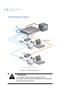
3) Reconnect the serial device Cable to one of the DB25F
connectors on the ECR Interconnect Cable as shown
on page 14.
4) Connect the PB3 Interface Cable (DB25M to DB9F) to the
remaining DB25F connector on the ECR Interconnect
Cable as shown on page 14. Connect the other end
(DB9F) to the DB9M connector on the PB3 unit (Port 2).
5) Connect the PB3 Power Supply to the unit, but do not plug
in the power.
Note: If only one (1) PB3 unit (one cash register) is to be connected, skip
to Step 9 below.