


Installation Preparation
8
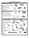
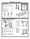
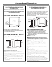
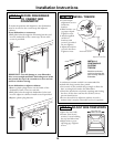
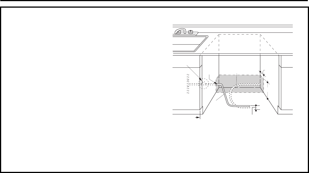
PREPARE HOT WATER LINE
The line may enter from either side, rear or floor
within the shaded area shown.
• The water line may pass through the same hole as
the electrical cable and drain hose. Or, cut an
additional 1-1/2" dia. hole to admit the line. If a
power cord with plug is used, it must pass through
a separate hole.
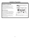
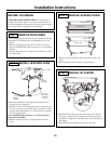
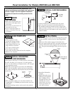
Water Line Connection
• Turn off the water supply.
• Install a hand shut-off valve in an accessible loca-
tion, such as under the sink. (Optional, but strongly
recommended and may be required by local codes.)
• The hot water line should be 3/8” O.D. copper
tubing or 1/2” O.D. plastic tubing. The line must
extend forward at least 30" from the left side or 40"
from the rear wall.
• The water line must be long enough to form a
smooth natural loop with no sharp bends or kinks
between the cutout entry.
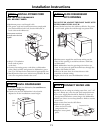
• Adjust water heater to deliver temperatures of 120°F to
150°F.
• Flush water line to clean out debris.
• The hot water supply line pressure must be 20-120 PSI.
6"
1-1/2"
Dia.
Hole
1-3/4"
2" from Floor
Cabinet Face
Hot
Shut-off Valve
Left
Side Entry
Approx. 30"
from Wall
Right Side Entry
Approx. 40"
from Wall