


Page
Introduction . . . . . . . . . . . . . . . . . . . . . . . . . . . . . . . . ii
Safety . . . . . . . . . . . . . . . . . . . . . . . . . . . . . . . . . . . . . .11
Equipment Inspection and Storage . . . . . . . . . .11
Final Equipment Inspection . . . . . . . . . . . . . . .11
Mounting . . . . . . . . . . . . . . . . . . . . . . . . . . . . . . .11
Installation . . . . . . . . . . . . . . . . . . . . . . . . . . . . . . . . . .12
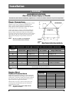
Power Connections . . . . . . . . . . . . . . . . . . . . . . .12
Engine Start Control Connections . . . . . . . . .12-3
Initial Energization . . . . . . . . . . . . . . . . . . . . .13-4
Control Connections . . . . . . . . . . . . . . . . . . . . . 5
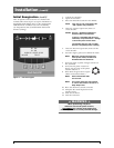
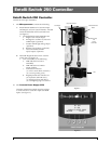
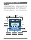
Entelli-Switch 250 Microprocessor Controller . . . . .16
Overview . . . . . . . . . . . . . . . . . . . . . . . . . . . . . . .16
LCD & Keypad . . . . . . . . . . . . . . . . . . . . . . . . . .17
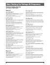
User Setting for Voltage & Frequency . . . . . . .1 8
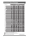
Accessory Group Packages. . . . . . . . . . . . . . . . . 9
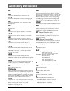
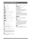
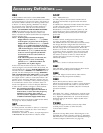
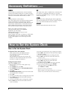
Accessory Definitions . . . . . . . . . . . . . . . . . . 10-13
How to Set the System Clock . . . . . . . . . . . . . . 13
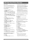
CDT One Event Timer Exerciser . . . . . . . . . . 14
CDP Clock Exerciser . . . . . . . . . . . . . . . . . . . . 15
User Setup - CFG Menu . . . . . . . . . . . . . . . . . . 16
User Setup - SET Menu . . . . . . . . . . . . . . . . . . 17
User Setup - System Info . . . . . . . . . . . . . . . . . 18
Bypass-Isolation Operation . . . . . . . . . . . . . . . . . . .121
100-400 Amps . . . . . . . . . . . . . . . . . . . . . . . . . .122
600-1200 Amps . . . . . . . . . . . . . . . . . . . . . . . . .123
1600-4000 Amps . . . . . . . . . . . . . . . . . . . . . . . .1 24
Page
Testing . . . . . . . . . . . . . . . . . . . . . . . . . . . . . . . . . . . .119
ATS Testing . . . . . . . . . . . . . . . . . . . . . . . . . . . .119
Standard Transition . . . . . . . . . . . . . . . . . . . . . 19
Delayed Transition . . . . . . . . . . . . . . . . . . . . . . 19
Sequence of Operation . . . . . . . . . . . . . . . . . . . . . . 20
Standard Transition . . . . . . . . . . . . . . . . . . . . .120
Delayed Transition . . . . . . . . . . . . . . . . . . . . . . 20
Controls Power Supply (CPS) . . . . . . . . . . . . . . . . . 21
Schematics, Standard & Delay . . . . . . . . . . . . .122
Troubleshooting & Diagnostics . . . . . . . . . . . . . . . . 23
Maintenance and Testing . . . . . . . . . . . . . . . . . . . . . 24
Inspection and Cleaning . . . . . . . . . . . . . . . . . 24
Servicing . . . . . . . . . . . . . . . . . . . . . . . . . . . . . .124
Testing . . . . . . . . . . . . . . . . . . . . . . . . . . . . . . . .124
ZBTSH/ZBTSDH . . . . . . . . . . . . . . . . . . . . . . . . . . . 25
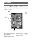
Standard Control Panel Layout (SSRCP) . . . . 25
Panel Mount Control Relays . . . . . . . . . . . . . .125
Sequence of Operation . . . . . . . . . . . . . . . . . . . . . . 26
Adjustments and Settings . . . . . . . . . . . . . . . . . . . . . 27
Solid State Timers . . . . . . . . . . . . . . . . . . . . . . .127
Voltage/Frequency Sensor (VSFM) . . . . . . . . .127
Solid State Phase Relay . . . . . . . . . . . . . . . . . . .127
Table of Contents
Authorized Service
For GE parts and service, call: 773 299-6600
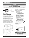
Introduction
GE Zenith Transfer Switches are used to provide a continuous
source of power for lighting and other critical loads by auto-
matically transferring from source 1 power to source 2 power
in the event that source 1 voltage falls below preset limits.
Voltage sensing and system control is performed via a
state-of-the-art microcontroller located on the cabinet door.
It is designed to give highly accurate control of the transfer
switch system.
All GE Zenith transfer switches are designed for use on
emergency or standby systems, and are rated for total
system or motor loads. Transfer switches are UL Listed
under Standard 1008 and CSA Certified under Standard
C22.2 No. 178 and IEC Listed under Standard 947.
NOTES:
A protective device such as a molded
case circuit breaker or fused disconnect
switch MUS
T be installed on both
sources of incoming power for circuit
protection and as a disconnection device.
All references made within this manual
about the term “S1” or “Source 1”
relate to a Normal Power Source.
All references made about the term “S2”
or “Source 2” relate to an Emergency
or Alternative Power Source.