


GE Zenith Controls 21
■
ZBTS / ZBTSD Operation and Maintenance Manual (71R-4000A)
Sequence of Operation
(cont’d)
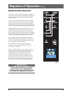
Bypass-Isolation Operation
An automatic transfer switch equipped with a bypass-isola-
tion switch provides the ability to withdraw the ATS for test-
ing and/or maintenance purposes without interrupting
the served load.
Operation of the unit is quick and convenient requiring
only one operator and less than one minute to complete.
Instructions are mounted on the front of each isolation
switch door along with a mimic panel providing indication
of power source availability and ATS/bypass switch positions.
The bypass switch is normally open on both sources with
the ATS feeding the system load. During operation, the
bypass is closed paralleling the ATS contacts which then
allows withdrawal of the ATS to the “TEST” or “ISOLATE”
positions. Mechanical and electrical interlocks are included
to prevent cross-servicing or bypassing to a dead source.
In the “TEST” position, the ATS is disconnected from
the load (now fed through the bypass) but control power
is present to allow complete operational testing through
the control panel of the transfer switch
In the “ISOLATE” position, the ATS is completely
withdrawn and may be removed from the enclosure
for maintenance if desired.
After the isolation operation, if the bypass is closed
on Source 1 and if this source fails, an auxiliary contact
on the bypass control will automatically start the
engine-generator set. When the second source is
available, the manual handle of the bypass may be
operated to transfer the load to the available source.
Interlocks prevent both this transfer, if the ATS is in
the circuit and connected to the opposite source or
reconnection of the ATS unless the positions match.
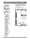
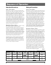
Figure 13
BYPASS
SOURCE 1
SOURCE 1
AVAILABLE
While the bypass switch is out of the AUTO
position/mode, the ATS is INHIBITED from
automatic operation. Make certain the ATS is left
in automatic after completion of any service.
WARNING