


2
NOTE ON NEUTRAL BONDED GENERATORS: Some portable generators are intended for use on jobsites, and therefore are subject to OSHA regulations for GFCI protection on all receptacles. These
"contractor grade" generators have their neutral wire bonded to the ground wire to pass OSHA inspection on job sites, and when connected to a transfer switch, this may cause nuisance tripping of the
generator GFCI breaker. If you’re using a neutral bonded generator to power a house or building through a transfer switch, then determine if the neutral bond wire on the generator can be disabled without
voiding the warranty, preferably by a dealer or a qualified electrician. NOTE: After this action, the generator will no longer pass OSHA inspection on job sites. Consult the manufacturer of your generator to
determine if the neutral bond can be removed. If it can be disabled, then no modifications to your transfer switch installation are needed. If the neutral bond cannot be disabled or voids the generator
warranty, you must install a Switched Neutral Kit (SNK) accessory with your transfer switch.
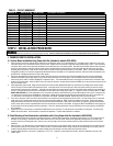
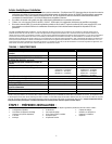
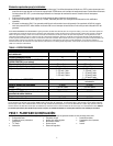
TABLE 1 - SPECIFICATIONS
Model: 6295
or 6378
6296 or 6380
# Circuits Provided on Transfer Switch
10 12
Max # Circuits
16 16
REQUIRED BREAKER FOR MAIN LOAD CENTER (not incl)
60 amp 2-pole 100 amp 2-pole
Utility Main Breaker
60 amp 2-pole 100 amp 2-pole
Generator Main Breaker
30 amp 2-pole 60 amp 2-pole
Breakers Provided with Unit
3– 15 amp 1-pole
3– 20 amp 1-pole
1– 20 amp 2-pole
1 --30 amp 2-pole
3– 15 amp 1-pole
3– 20 amp 1-pole
1– 20 amp 2-pole
1 --30 amp 2-pole
1 – 50 amp 2-pole
Max GEN Watts
7500 continuous / 9000 surge 12500 continuous / 18000 surge
Max GEN Amps
30 Amps 60 amps
Voltage
125/250 Volts 125/250 Volts
NEMA Type Enclosure
1 – Indoor Only 1 – Indoor Only
NEMA Configuration of Male Inlet in Power Inlet Box
NEMA L14-30 CS-6365
Phase
1 1
Minimum Gauge Cord Size
10/4 AWG 6/4 AWG
*Note: If Ground Fault Circuit Interrupters (GFCI), Arc Fault Circuit Interrupters (AFCI), or Surge Protector Circuit Breakers were used as the branch circuit protector in the main load center, they
MUST be used in the transfer switch. GFCI and AFCI breakers require an isolated neutral connected from the load to the GFCI or AFCI. The load neutral needs to be connected with a wire nut to a
3-6 foot piece of white wire, run through the harness conduit to the transfer switch and connected to the "load neutral" lug or pigtail on the GFCI or ACFI breaker. Because GFCI and AFCI circuit
breakers can take up more than one space, the overall maximum number of circuits may be reduced from the number shown.
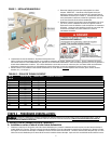
STEP 1: PLANNING YOUR INSTALLATION:
1. Determine the appliances, circuits or equipment you want to operate with generator power during a power outage, such as:
• Refrigerator/Freezer,
• Furnace Blower (gas/oil only)
• TV / Radio
• Lighting
• Water Heater
• Garage Door Opener
• Microwave, Coffee Maker
• Well Pump
• Security System
• Sump Pump
• Computer, Fax and Printer, Phone
• Aquarium
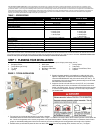
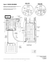
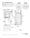
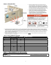
FIGURE 1: TYPICAL INSTALLATION
2. Determine the amps required for each appliance by reading the label on the
appliance. IMPORTANT: No appliance should have an amperage rating that
exceeds the GEN MAIN breaker rating in the transfer switch (See Table 1). The
total amperage of all circuits can exceed the generator rating, but not all circuits
will be able to be used concurrently.
3. Assign the circuit # in the load center to a circuit (A2, B2, etc.) in the transfer
switch matching the size of the circuit breaker in the load center to the circuit
breaker in the transfer switch. Once you’ve determined which circuits you want
to connect and the appropriate amperage, you will be ready to begin installing
your transfer switch.
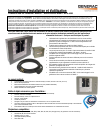
4. The location of your load center/electrical panel in your home or business
will determine where the transfer switch will be installed. Refer to Figure 1. In addition to the transfer switch, this kit includes a generator cord and power inlet
box. You will use the generator cord to connect your generator to the power inlet box outdoors. Whether your load center is in a basement, interior room or
garage, we recommend installing power inlet box on the exterior of your house or building to avoid running generator cord through a door or window.
5. Determine where you will install the power inlet box on an exterior wall at least 5 feet from any openings (doors, windows, vents, etc.). See Figure 1.