


3
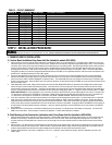
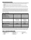
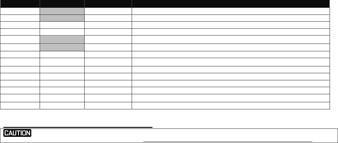
TABLE 2 – CIRCUIT WORKSHEET
CIRCUIT # 6295 or 6378 6296 or 6380 APPLIANCE OR CIRCUIT
A1 NA 50A
B1 NA 50A
A2 30A 30A
B2 30A 30A
A3 NA 20A
B3 NA 20A
A4 15A 20A
B4 20A 15A
A5 15A 20A
B5 20A 20A
A6 20A 15A
B6 15A 15A
A7 20A NA
B7 20A NA
STEP 2: INSTALLATION PROCEDURE:
HAZARDOUS VOLTAGES ARE PRESENT INSIDE TRANSFER SWITCH ENCLOSURES THAT CAN CAUSE DEATH OR SEVERE PERSONAL INJURY. FOLLOW PROPER INSTALLATION,
OPERATION AND MAINTENANCE PROCEDURES TO AVOID HAZARDOUS VOLTAGES. TURN OFF THE MAIN CIRCUIT BREAKER IN THE LOAD CENTER BEFORE STARTING INSTALLATION.
I. TRANSFER SWITCH INSTALLATION:
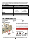
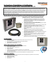
A: Surface Mount Installation Using Power Inlet Box (included in models 6295-6296)
1. Select a location on the left or right side of the Load Center to mount transfer switch, as it is provided with 21.5” of flexible conduit. Remove the cover to the
load center and the cover of the transfer switch, save the screws. Measure and cut conduit to a length and snap provided fittings on ends. Locate and remove
a knockout (KO) on lower side of load center that matches the conduit fitting size on the wiring harness. After attaching the flexible conduit to both enclosures
through one of the bottom or side KOs, hold the transfer switch in position against the wall on which it is to be mounted, mark the holes on the wall for the
anchoring screws and anchor to wall (anchors not provided). Be sure NOT to stress the flexible conduit, as it may break. [NOTE: The Electrical Non-Metallic
Tubing (ENT) provided is UL Listed and recognized by the National Electrical Code (NEC) for this application. However, some local codes and inspectors may
prohibit its use in buildings that exceed (3) floors above grade.]
2. Fish the pre-assembled wire harness through the conduit. Strip each wire in the wire harness 5/8” and insert and tighten the wires to the correspondingly
marked circuit breakers in the transfer switch. As you attach each marked wire to the circuit breaker, write the appliance name on the label on the transfer
switch cover per the TABLE 2 CIRCUIT WORKSHEET completed in Step 1. The unmarked BLACK wires in the harness are inserted into the UTIL MAIN 2-pole
breaker in the transfer switch. Attach the WHITE wire to the neutral bar located on the right side and attach the GREEN wire to the ground bar located on the left
side of the transfer switch.
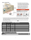
3. Install appropriately sized conduit, fittings and wire between the Power Inlet Box (Models 6295-6296 only) mounted on the building exterior and the transfer
switch, referring to Power Inlet Box Install Instructions below. Locate and remove a KO on the right top or side of the transfer switch, pull wire into transfer
switch enclosure and secure wire with fitting. . Install the green ground wire into the ground bar on the left, and install the white neutral wire into neutral bar on
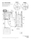
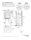
the right. Using provided wiring connectors, connect black wire from PIB to black wiring going to Meter “A”. Repeat for red wire from PIB to Meter “B”. Note:
Models 6296 and 6380 use current transformers (CTs) connected to the meters; pass the black wire from the PIB through the hole in the CT connected to the
“A” meter before connecting to the “GEN MAIN A” circuit breaker. Repeat for the red wire from the PIB, passing through the hole in the CT connected to the
“B” meter before connecting to the “GEN MAIN B” circuit breaker. See FIGURE 2 WIRING DIAGRAM. Reinstall the cover to the transfer switch.
4. In the main Load Center, remove the wires from the breakers for the loads that will be relocated to the transfer switch. Cut each harness wire to a convenient
length, strip off 5/8” insulation and connect to the wires removed from the breakers per TABLE 2 with the provided wire connectors. Remove two adjacent
single pole breakers from which the load wires were removed and install the NEW 60A or 100A 2-pole circuit breaker (as required in the Other Items Needed
section) in their place. Insert the unmarked BLACK wires from the harness into the new circuit breaker. Terminate the WHITE and GREEN wire in the harness in
an open position in the Neutral and Ground bars respectively. If there is no separate ground bar, insert the GREEN wire into an open position in the NEUTRAL
bar, and tighten.
5.
Reinstall the cover to the load center, and turn ON the MAIN breaker in the load center. Turn ON all branch circuit breakers in both panels. Turn ON the UTIL
MAIN in the transfer switch. Check that power is restored to all appliances. Transfer switch installation is complete.
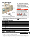
B. Flush Mounting in New Construction (unfinished walls) Using Power Inlet Box (included in 6295-6296):
1. Install the transfer switch at the same time as the main load center, in adjacent wall stud openings (the transfer switch enclosure is 14.25” wide and will fit in
standard 16” wall framing). Remove the transfer switch dead front cover, save the screws. Knock out the appropriate mounting slots on the sides of the
enclosure and secure to framing with nails or screws; be sure the front edge of the enclosure extends forward to be flush with the thickness of the finished
wallboard.
2. Mark and drill a 2 1/8” diameter hole in the stud between the main load center and the transfer switch, lining up with the lowest side KO in the load center and
near the bottom center KO in the transfer switch. Remove the KO’s, cut the provided conduit to length, snap on the provided fittings to the conduit, push the
conduit through the drilled hole and install the conduit assembly to the KO openings in the main load center and transfer switch.
3. Complete Section IA3 above. Cut a piece of cardboard to 14.5” x 12.5”, using the 4 screws removed in step IIA1, attach the cardboard to the front of the
transfer switch.