


4
4. After the walls have been finished and painted, remove the cardboard cover and complete the installation as described in Sections IA2, 4 and 5. NOTE: To
simplify installation, all conductors for the branch circuits can be terminated directly into the transfer switch instead of the main load center, eliminating the
need to install the harness wires between the main load center and transfer switch for each circuit.
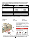
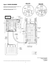
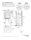
C. Flush Mounting in Retrofit Construction (finished walls) Using Power Inlet Box (included in 6295-6296):
1. Remove the dead front cover from the main load center and the transfer switch, save the screws.
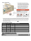
2. Determine where to install the transfer switch (keep in mind the length and flexibility of the conduit provided and where the generator wires will enter), Verify
that there are no wires going thru the side of the main load center into the space where you want to mount the transfer switch. Use a “stud finder” to determine
if you have at least 14.25” between the studs to mount the transfer switch. Hold the transfer switch enclosure in the desired position on the wall and mark the
exact dimensions of the box. Set the enclosure aside and cut the hole in the wallboard.
3. Remove a 1” or 1-¼” KO in the lower side (towards the hole cut in Step 2) of the load center. From the inside of the main load center, drill a ¼” pilot hole
through the stud in the center of the KO removed. Reach down inside the hole cut in Step 2 and drill a 2 1/8” diameter hole in the stud using the pilot hole as a
guide. Remove the bottom center KO in the transfer switch, snap the fittings on the conduit, and attach the conduit assembly to the transfer switch.
4. Remove one of the KO’s on the top of the transfer switch enclosure and install an appropriately sized fitting for the incoming wires form the Power Inlet Box.
Knock out the appropriate mounting slots on the sides of the transfer switch enclosure.
5. Insert the transfer switch enclosure into the hole in the wallboard, inserting conduit fitting on attached conduit assembly into the KO removed in Step 3. Fasten
conduit fitting to main load center with locknut. Secure transfer switch enclosure to framing with nails or screws; be sure the front edge of the enclosure
extends forward to be flush with the finished wallboard.
6. Complete Section IA2 thru 5 above.
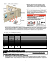
II. EXPANDING OR RECONFIGURING YOUR TRANSFER SWITCH:
This transfer switch ships from the factory with certain popular branch circuit breaker sizes. However, the circuit breaker assortment can be modified to suit specific
requirements, and this does not void the UL Listing. For example, if the 2-pole 20 amp circuit breaker is not needed, it may be removed from the panel and replaced
with any combination of the following: two separate full size breakers, four tandem (half size) breakers, one full size and two tandems, or a quad breaker. If
additional circuit(s) are added, the installer is responsible for providing appropriately sized wire(s) for each circuit.
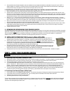
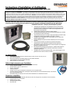
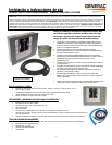
III. INSTALLING THE POWER INLET BOX (Included in Models 6295-6296)
1. Remove the front cover of the Power inlet box. Remove the 3 screws that secure the flanged inlet to the bottom plate. For
installations where side clearance exceeds 12” on both sides, remove the 4 screws that secure the bottom plate to the box.
2. Mount the power inlet box on the outside of the building in a convenient location (minimum 24” above grade), using the four holes
provided in the back of the enclosure. Use sealant around the anchoring screws to keep water from entering the box at these
mounting holes. Using approved wiring methods, install the wiring through one of the knockouts provided in the enclosure. Be
sure to seal around the hole in the building where the conduit enters through the wall.
3. Extend wiring inside the power inlet box approx. 8” from the point of entrance. Attach green or bare ground wire to green lead
provided in power inlet box with wire nut (provided by installer). Strip and insert incoming leads into terminals on flanged inlet.
Insert white wire (neutral) into nickel-plated screw terminal or white marking on the flanged inlet.
4. Carefully fold wires into the enclosure and reattach the bottom assembly or inlet onto box with screws removed earlier. Installation is complete.
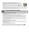
STEP 3: USING YOUR TRANSFER SWITCH:
NEVER run portable generators indoors or in garages, basements, or sheds. Portable generators should always be used at least 5 feet away from windows, doors, vents, or any other
opening. Carbon Monoxide (CO) from a generator is deadly and can kill you in minutes. Read and follow all generator directions before use.
A. Transferring from Utility Power to Generator Power:
1. Move generator outdoors. Connect male plug of Power Cord into 125/250V receptacle on the generator. Turn ON circuit breaker for the outlet plugged into.
2. Plug in female connector of the Power Cord to the Power Inlet Box. Turn all circuit breakers in the transfer switch to their OFF position.
3. Start the generator outdoors, following the procedures described in the generator’s owner’s manual.
4. Turn ON the GENERATOR MAIN circuit breaker in the transfer switch. Turn ON circuit breakers in the manual transfer switch one at a time alternating from
phase “A” and phase “B”. Watch the meters as you turn on successive circuits so that the meters do not continuously exceed the maximum wattage of the
generator. It may be necessary to alternate the use of larger loads (furnace motors, well pumps, freezers, etc.) to avoid overloading the generator. To
promote generator life, loads should be balanced on Phase “A” and “B” so that the wattage reading on each meter is within about 1000 watts of the other.
5. Test your circuits by using the wattmeters or determine wattage from that shown on each appliance. Make a note of any excessive loads which must be
removed from a given circuit during generator operation in an emergency. [Note: Wattmeters do not show power at very low levels.]
B. Transferring from Generator Power to Utility Power:
1. On the transfer switch, turn the GENERATOR MAIN breaker OFF. Then shut down the generator, following the procedures in the generator Owner’s Manual.
2. On the transfer switch, turn the UTILITY MAIN breaker ON. Then Turn ON any branch circuit breakers in the transfer switch that are OFF.
3. Unplug the power cord from the generator and the power inlet.
4. Cool off the generator and store in a dry, secured location.
To ensure that your generator will work properly when you need it, it is important to start and run your generator under load regularly and keep the tank filled with
fresh fuel. Perform the above steps at least ONCE A MONTH to keep the generator properly “exercised.” It is not necessary to turn off any circuits in the MAIN
load center when operating/testing the transfer switch.