


2
Section 1 — General Information
ATS “HS” Type Transfer Switch
1.1 INTRODUCTION
This manual has been prepared especially for the
purpose of familiarizing personnel with the design,
application, installation, operation and servicing of
the applicable equipment. Read the manual carefully
and comply with all instructions. This will help to
prevent accidents or damage to equipment that might
otherwise be caused by carelessness, incorrect appli-
cation, or improper procedures.
Every effort has been expended to make sure that the
contents of this manual are both accurate and cur-
rent. The manufacturer, however, reserves the right
to change, alter or otherwise improve the product at
any time without prior notice.
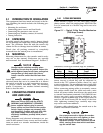
1.2 EQUIPMENT DESCRIPTION
The automatic transfer switch is used for transfer-
ring electrical load from a UTILITY (NORMAL) power
source to a EMERGENCY ( STANDBY) power source.
Such a transfer of electrical loads occurs automati-
cally when the UTILITY power source has failed or is
substantially reduced and the EMERGENCY source
voltage and frequency have reached an acceptable
level. The transfer switch prevents electrical feedback
between two different power sources (such as the
UTILITY and EMERGENCY sources) and, for that
reason, codes require it in all standby electric system
installations.
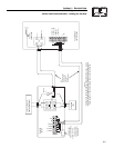
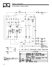
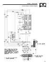
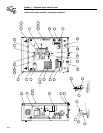
The transfer switch consists of a transfer mecha-
nism, a relay control, and a terminal strip for con-
nection of sensing wires.
This switch is suitable for control of motors, electric
discharge lamps, tungsten filament and electric heat-
ing equipment and the tungsten load does the switch
rating.
The transfer switch is for use in optional standby sys-
tems only.
The transfer switch is suitable for use on a circuit
capable of 10,000 rms symmetrical amperes, 240
VAC when protected by a circuit breaker without an
adjustable short time response or by fuses.
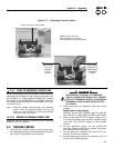
1.3 TRANSFER SWITCH DATA DECAL
A DATA DECAL is permanently affixed to the transfer
switch enclosure. Use this transfer switch only with
the specific limits shown on the DATA DECAL and on
other decals and labels that may be affixed to the
switch. This will prevent damage to equipment and
property.
When requesting information or ordering parts for this
equipment, make sure to include all information from
the DATA DECAL.
Record the Model and Serial numbers in the space pro-
vided below for future reference.
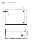
1.4 TRANSFER SWITCH ENCLOSURE
The standard switch enclosure is a National
Electrical Manufacturer’s Association (NEMA) 3R
type. NEMA 3R type enclosures primarily provide a
degree of protection against falling rain and sleet and
is not damaged by the formation of ice on the
enclosure.
1.5 SAFE USE OF TRANSFER SWITCH
Before installing, operating or servicing this equip-
ment, read the SAFETY RULES (inside front cover)
carefully. Comply strictly with all SAFETY RULES to
prevent accidents and/or damage to the equipment.
The manufacturer recommends that a copy of the
SAFETY RULES are posted near the transfer switch.
Also, be sure to read all instructions and information
found on tags, labels and decals affixed to the equip-
ment.
Two publications that outline the safe use of transfer
switches are the following:
• NFPA 70; National Electrical Code
• UL 1008, STANDARD FOR SAFETY-AUTOMATIC
TRANSFER SWITCHES
MODEL #
SERIAL #