


4
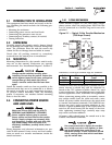
Section 3 — Operation
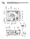
ATS “HS” Type Transfer Switch
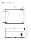
Connect power source load conductors to clearly
marked transfer mechanism terminal lugs as follows
1. Connect UTILITY (NORMAL) power source cables
to switch terminals N1, N2.
2. Connect EMERGENCY (STANDBY) source power
cables to transfer switch terminals E1, E2.
3. Connect customer LOAD leads to switch termi-
nals T1, T2.
Conductors must be properly supported, of approved
insulative qualities, protected by approved conduit,
and of the correct wire gauge size in accordance with
applicable codes.
Be sure to maintain proper electrical clearance
between live metal parts and grounded metal. Allow
at least 1/2 inch for 100-400 amp circuits.
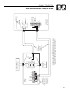
2.5 CONNECTING START CIRCUIT
WIRES
Control system interconnections (Section 6) consist
of UTILITY 1 (N1) and UTILITY 2 (N2), LOAD 1 (T1)
and LOAD 2 (T2), and leads 23 and 194 when used
in conjunction with some water-cooled generators.
Recommended wire gauge sizes for this wiring
depends on the length of the wire, as recommended
below:
NOTE:
If there are no matching terminal connections for
LOAD 1 (T1) and LOAD 2 (T2) in the generator
control panel, do not connect these wires. Failure
of the control board will occur if connected.
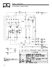
3.1 FUNCTIONAL TESTS AND
ADJUSTMENTS
Following transfer switch installation and inter-
connection, inspect the entire installation careful-
ly. A competent, qualified electrician should
inspect it. The installation should comply strictly
with all applicable codes, standards, and regula-
tions. When absolutely certain the installation is
proper and correct, complete a functional test of
the system.
Perform functional tests in the exact order
presented in this manual, or damage could be
done to the switch.
IMPORTANT: Before proceeding with functional
tests, read and make sure all instructions and infor-
mation in this section are understood. Also read the
information and instructions of labels and decals
affixed to the switch. Note any options or accessories
that might be installed and review their operation.
3.2 MANUAL OPERATION
Do NOT manually transfer under load.
Disconnect transfer switch from all power
sources by approved means, such as a main
circuit breaker(s).
A manual HANDLE is shipped with the transfer
switch. Manual operation must be checked BEFORE
the transfer switch is operated electrically. To check
manual operation, proceed as follows:
1. Turn the generator’s AUTO-OFF-MANUAL switch
to OFF.
2. Turn OFF both UTILITY and EMERGENCY
power supplies to the transfer switch, with what-
ever means provided (such as the main line cir-
cuit breakers).
3. Note position of transfer mechanism main con-
tacts by observing the moveable contact carrier
arm.
• Manual operation handle towards the top of
switch mechanism - LOAD terminals (T1, T2) are
connected to UTILITY terminals (N1, N2).
• Manual operation handle towards the bottom of
switch mechanism - LOAD terminals (T1, T2) are
connected to EMERGENCY terminals (E1, E2).
Do not use excessive force when operating
the transfer switch manually or damage could
be done to the manual handle.
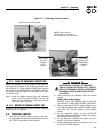
3.2.1 CLOSE TO NORMAL SOURCE SIDE
Before proceeding, verify the position of the switch by
observing the position of manual operation handle in
Figure 3.1. If the handle is UP, the contacts are closed
in the NORMAL position, no further action is
required. If the handle is DOWN, proceed with Step
1.
Step 1: With the handle inserted into the actuating
shaft, move handle UP. Be sure to hold on to
the handle as it will move quickly after the
center of travel.
◆
!
!
DANGER
!
MAXIMUM WIRE LENGTH RECOMMENDED WIRE
SIZE
460 feet (140m) No. 18 AWG.
461 to 730 feet (223m) No. 16 AWG.
731 to 1,160 feet (354m) No. 14 AWG.
1,161 to 1,850 feet (565m) No. 12 AWG.