


5
3.2.2 CLOSE TO EMERGENCY SOURCE SIDE
Before proceeding, verify the position of the switch by
observing the position of the manual operation han-
dle in Figure 3.1. If the handle is DOWN, the contacts
are closed in the EMERGENCY (STANDBY) position.
No further action is required. If the handle is UP, pro-
ceed with Step 1.
Step 1: With the handle inserted into the actuating
shaft, move the handle DOWN. Be sure to
hold on to the handle as it will move quickly
after the center of travel.
3.2.3 RETURN TO NORMAL SOURCE SIDE
Manually actuate switch to return manual operating
handle to the UP position.
3.3 VOLTAGE CHECKS
1. Turn ON the UTILITY power supply to the trans-
fer switch with whatever means provided (such as
the UTILITY main line circuit breaker).
PROCEED WITH CAUTION. THE TRANSFER
SWITCH IS NOW ELECTRICALLY HOT. CONTACT
WITH LIVE TERMINALS RESULTS IN EXTREMELY
HAZARDOUS AND POSSIBLY FATAL ELECTRI-
CAL SHOCK.
2. With an accurate AC voltmeter, check for correct
voltage.
Single-phase utility supply:
Measure across ATS terminal lugs N1 and N2.
Also check N1 to NEUTRAL and N2 to NEUTRAL.
3. When certain that UTILITY supply voltage is cor-
rect and compatible with transfer switch ratings,
turn OFF the UTILITY supply to the transfer
switch.
4. On the generator panel, set the AUTO-OFF-
MANUAL switch to MANUAL position. The gener-
ator should crank and start.
5. Let the generator stabilize and warm up at no-
load for at least five minutes.
6. Set the generator's main circuit breaker (CB1) to
its ON or CLOSED position.
DANGER
◆
◆
Section 3 — Operation
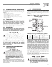
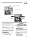
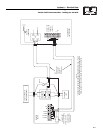
ATS “HS” Type Transfer Switch
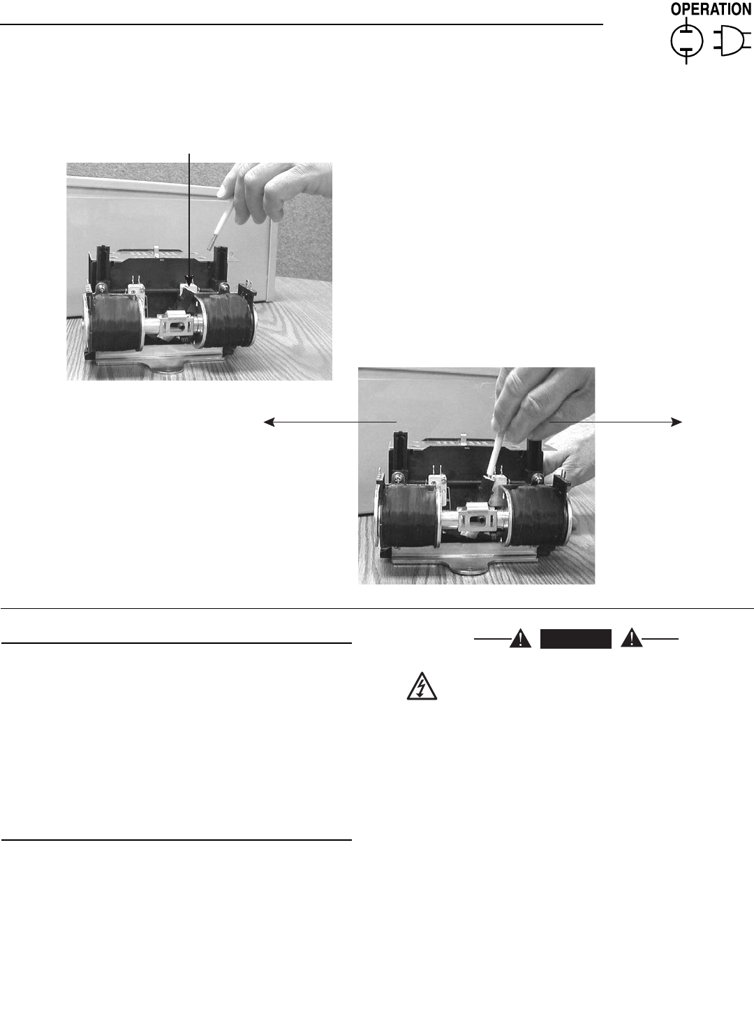
Attach handle to actuating shaft.
Move handle
UP for the
NORMAL
(UTILITY)
position.
Move handle
DOWN for the
EMERGENCY
(STANDBY)
position.
NOTE: Return handle to
storage position in enclosure
when finished with manual transfer.
Figure 3.1 — Actuating Transfer Switch