


2
Planning Your Transfer Switch Installation:
1. Determine the appliances, circuits or equipment you want to operate with generator power during a power outage, such as:
• Refrigerator/Freezer
• Furnace Blower (gas/oil only)
• TV / Radio
• Lights
• Water Heater
• Garage Door Opener
• Microwave, Coffee Maker
• Well Pump
• Security System
• Sump Pump
• Computer, Fax and Printer
• Cordless Telephone
2. Determine the amps required for each appliance by reading the label on the appliance. IMPORTANT: No appliance should have
an amperage rating that exceeds the individual breaker rating in the transfer switch. The total amperage of all circuits can exceed
the generator rating, but not all circuits will be able to be used concurrently. Do not connect a 50-amp circuit (such as central air
conditioning or Electric Range) to this system. GenTran is not responsible for accidents or property damage due to incorrect or
inappropriate installation.
3. Assign the circuit # in the load center and in the GenTran
®
transfer switch, matching the size of the circuit breaker in the load
center to the circuit breaker in the transfer switch. Once you’ve determined which circuits you want to connect and the
appropriate amperage, you will be ready to begin installing your GenTran
®
transfer switch.
4. The location of your load center/electrical panel in your home or business will determine where the GenTran
®
transfer switch will
be installed. Refer to the illustrations below. In addition to the transfer switch, you may need additional accessories to complete
your generator transfer switch installation, such as a generator cord and power inlet box. A generator cord (sold separately) is
needed to connect your generator to the GenTran
®
transfer switch or power inlet box. If your load center is in your garage, we
recommend at least a 25-foot generator cord to reach from your generator outside the garage on the driveway to the transfer
switch. NEVER run a generator in an enclosed area! If your load center is in a basement or interior room, you shall install a
power inlet box (sold separately) on the exterior of your house or building to avoid running the generator cord through a door or
window. Once you have all of the essential components for your specific needs, you may proceed with the installation.
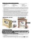
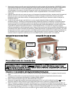
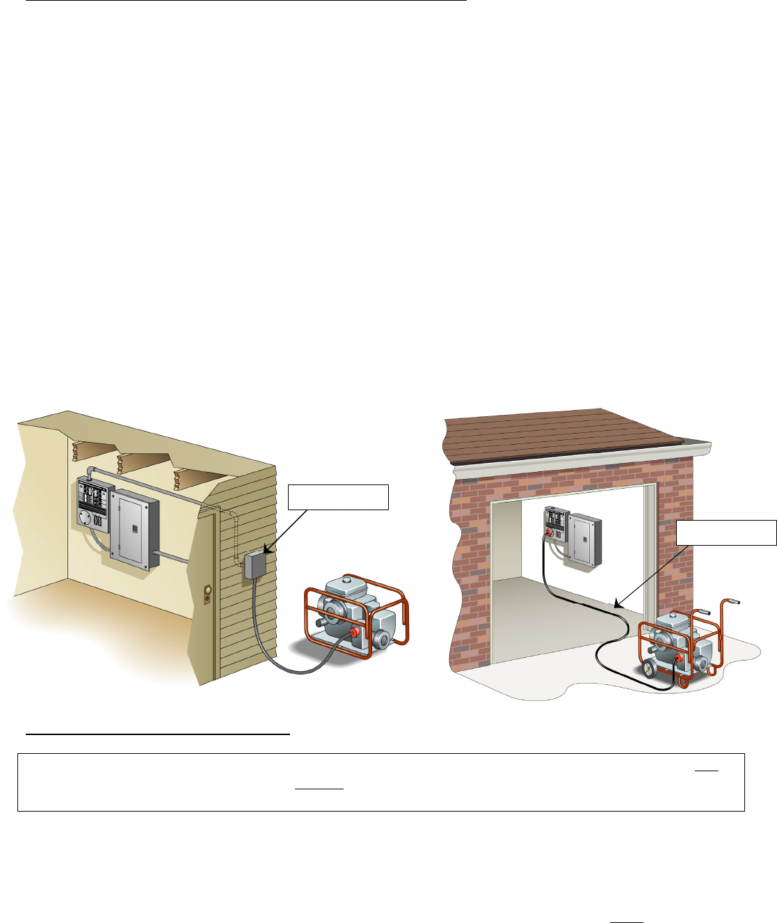
HARDWIRED/BASEMENT INSTALLATION: TYPICAL GARAGE INSTALLATION:
Installation Procedure:
IMPORTANT: Please read this entire procedure before beginning installation. WARNING: For SAFETY, turn OFF
the MAIN circuit breaker in the load center BEFORE starting installation. Remember, the wiring ahead of the
MAIN is HOT, even when the main circuit breaker is off.
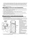
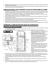
Installations with a Generator Cord Connection (Garage Installations):
1. Select a location on right or left side of load center approximately 12 inches to the side of the load center.
2. Find a knockout (KO) on the lower side of the load center that matches the conduit fitting size provided with the Transfer Switch
(1” on both models).
3. Remove the cover from the load center and the knockout selected in step 2.
4.
Determine if the conduit length provided needs to be shortened. If so, remove the wires from the conduit before cutting to avoid
damaging the wires. Then use a utility knife to cut conduit to desired length. . [
NOTE: The Electrical Non-Metallic Tubing (ENT)
Power Inlet Box
25 ft. Power Cord