


3
is UL Listed and recognized by the National Electrical Code (NEC). However, it generally cannot be used in buildings that exceed
(3) floors above grade. While the NEC does allow its use for this application, local codes and inspectors may prohibit its use in
your area. If this situation exists, call 888-GEN-TRAN to request a length of flexible metal conduit (FMC) to use in its place.]
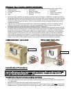
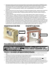
5. Assemble the conduit to the load center and transfer switch after putting the wire harness through the selected knockout in the
load center.
6. Without stressing the flexible conduit, turn the transfer switch to a vertical position, use the enclosed template to mark the hole
locations, and anchor the unit to the wall.
Hardwired Installations from a Power Inlet Box to the Transfer Switch (Basement Installations):
1. Follow steps 1 thru 6 above.
2. To remove the male inlet from lower front of transfer switch, remove the three (3) screws that secure it to the frame. Pull it
directly out. Then loosen the screws that secure the wires into the flanged inlet. Remove and set aside the four (4) screws (2 on
the top, 2 on the bottom) securing the cover. Pull off the cover.
3. Five (5) ½” knockouts are provided for easy wiring using Romex or conduit. Locate and remove your desired knockout. Then
insert connector and locknut followed by the wires.
4. Feed sufficient wire into the transfer switch so that it can be pulled 4” through the removed inlet hole.
5. Connect the wires you just fed through to the four wires removed from the male inlet using wire connectors (provided by
installer). Connect black to black, red to red, and so on.
6. Push wires and wirenuts back into the cavity in the lower portion of the transfer switch. Use the closing plate provided in the
hardware kit to cover the hole left by removing the male inlet.
7. Neatly route the Romex out to the Power Inlet Box. Be sure to secure it according to code along the way.
Wiring your GenTran
®
Transfer Switch to the Load Center:
1. Please note on the transfer switch that each circuit breaker is rated at 15 amps, 20 amps or 30 amps (on model 3028 only).
2. Installer MUST select the same breaker size in the load center for each circuit in the transfer switch (ie: 15 amps only with 15
amps, 20 amps only with 20 amps, etc.).
3. It is recommended that the MAIN circuit breaker in the Load Center be turned OFF while connecting the wires from the transfer
switch to those in the Load Center. Remember that the wires ahead of the MAIN BREAKER are still HOT, and could cause serious
injury or death if not handled properly. Use extreme CAUTION when wiring inside a LIVE load center.
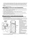
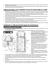
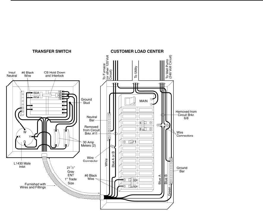
4. From the harness wires now in the load
center, locate wire A4. Then select a
desired circuit breaker in the load center
with the same rating (ex: 15 amps). See
Wiring Diagram at left.
5. Turn off this selected breaker and remove
the wire from the breaker in the LC.
Connect Blue wire using a wirenut to the
wire removed from the breaker.
6. Locate the blue wires with the
corresponding markings (ie: A5, B5, A6, B6,
etc.) turn OFF the appropriate breaker(s) in
the Load Center, remove the wire(s) from
the breaker(s) cut to a convenient length,
strip each 5/8”, and connect them to the
desired wire from the transfer switch using
wire connectors.
7. Follow this procedure for each of the
remaining circuits. (Blue connected using
wirenuts to the wire removed from the
breaker).
8. Find the White wire from the transfer
switch. Strip 5/8”, and insert into an
unused hole in the Neutral bar.
9. Find the Green wire from the transfer switch. Strip 5/8”, and insert into the ground bar in the Load Center or if there is no ground
bar, insert it into an unused hole in the neutral bar.
Model 3028