- 17 -
Hardware Installation Process
English
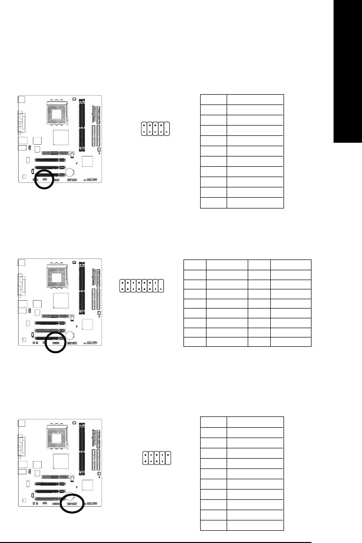
12) COMB (COM B Connector)
Be careful with the polarity of the COMB connector. Check the pin assignment carefully while you
connect the COMB cable, incorrect connection between the cable and connector will make the device
unable to work or even damage it. For optional COMB cable, please contact your local dealer.
13) GAME (Game Connector)
This connector supports joystick, MIDI keyboard and other relate audio devices. Check the pin assign-
ment while you connect the game cables. Please contact your nearest dealer for optional game cables.
Pin No. Definition
1 NDCDB-
2 NSINB
3 NSOUTB
4 NDTRB-
5 GND
6 NDSRB-
7 NRTSB-
8 NCTSB-
9 NRIB-
10 No Pin
19
2
10
115
2
16
Pin No. Definition
1 VCC
2 GRX1_R
3 GND
4 GPSA2
5 VCC
6 GRX2_R
7 GRY2_R
8 MSI_R
Pin No. Definition
9 GPSA1
10 GND
11 GRY1_R
12 VCC
13 GPSB1
14 MSO_R
15 GPSB2
16 No Pin
14) F_USB1 / F_USB2 (Front USB Connector)
Be careful with the polarity of the front USB connector. Check the pin assignment carefully while you
connect the front USB cable, incorrect connection between the cable and connector will make the de-
vice unable to work or even damage it. For optional front USB cable, please contact your local dealer.
Pin No. Definition
1 Power
2 Power
3 USB Dx-
4 USB Dy-
5 USB Dx+
6 USB Dy+
7 GND
8 GND
9 No Pin
10 NC
1
9
2
10


