


23
Hardware Installation Process
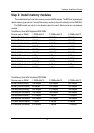
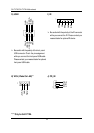
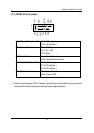
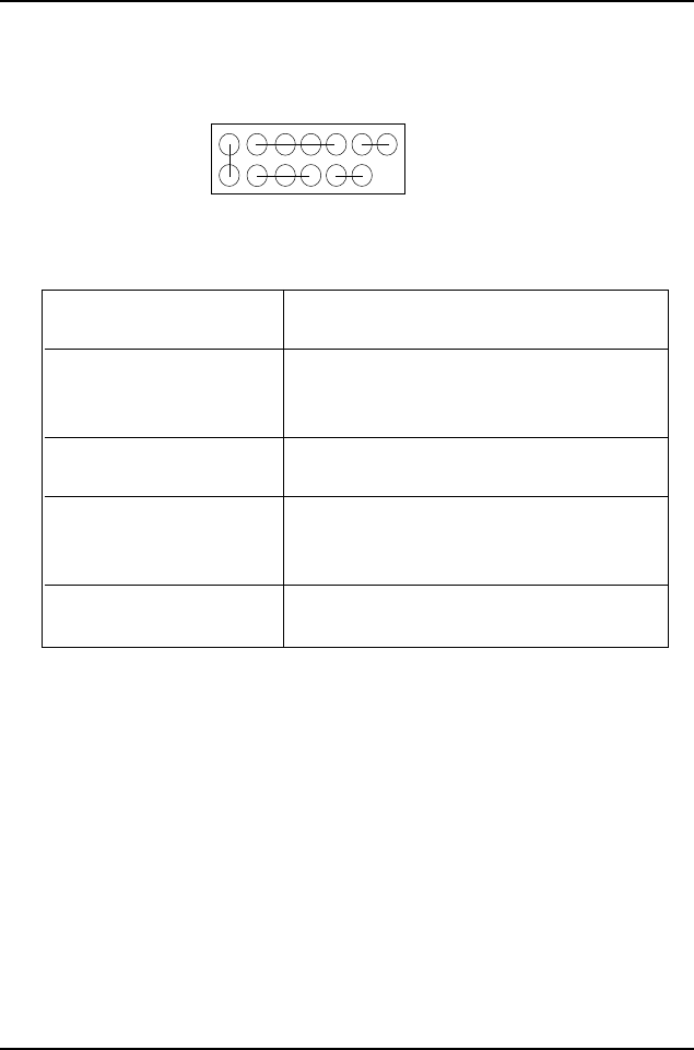
F) F_PANEL (2x7 pins jumper)
Please connect the power LED, PC speaker, reset switch and power switch etc of your chassis
front panel to the front panel jumper according to the pin assignment above.
HD (IDE Hard Disk Active LED) Pin 1: LED anode(+)
Pin 2: LED cathode(-)
SPK (Speaker Connector) Pin 1: VCC(+)
Pin 2- Pin 3: NC
Pin 4: Data(-)
RST (Reset Switch) Open: Normal Operation
Close: Reset Hardware System
PD+/PD_G/PD_Y(Power LED) Pin 1: LED anode(+)
Pin 2: LED cathode(-)
Pin 3: LED cathode(-)
PW (Soft Power Connector) Open: Normal Operation
Close: Power On/Off
HD+
PD_Y
214
1
13
HD-
PD_G
PD+
PW-
PW+
RST+
RST-
SPK+
SPK-
1
1