


- 28 -GA-K8VT800M Motherboard
English
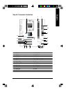
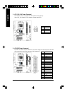
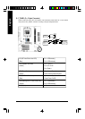
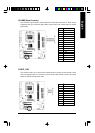
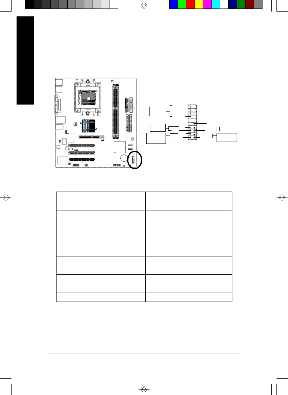
9) F_PANEL (2 x 10 pins Connector)
Please connect the power LED, PC speaker, reset switch and power switch etc. of your chassis
front panel to the F_PANEL connector according to the pin assignment above.
HD (IDE Hard Disk Active LED) Pin 1: LED anode(+)
(Blue) Pin 2: LED cathode(-)
SPK (Speaker Connector) Pin 1: VCC(+)
(Amber) Pin 2- Pin 3: NC
Pin 4: Data(-)
RES (Reset Switch) Open: Normal Operation
(Green) Close: Reset Hardware System
PW (Soft Power Connector) Open: Normal Operation
(Red) Close: Power On/Off
MSG(Message LED/ Power/ Sleep LED) Pin 1: LED anode(+)
(Yellow) Pin 2: LED cathode(-)
NC (Purple) NC
1
2
1920
HD-
RES+
RES-
NC
SPEAK-
MSG-
MSG+
PW-
PW+
Speaker
Connector
SPEAK+
1
1
1 1
1
HD+
IDE Hard Disk
Active LED
Reset Switch
Message LED/
Power/
Sleep LED
Soft Power
Connector