


2
GS-SR125EDL Rack mount Server
Table of Content
Safety, Care and Regulatory Information ........................................... 4
Introduction ..................................................................................... 8
Contents Packages ......................................................................... 8
WARNING! ...................................................................................... 8
Chapter 1 Features Summary ........................................................... 9
Chapter 2 System Hardware Installation ...........................................11
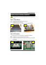
Step 2-1: Chassis Removal ......................................................................... 11
Step 2-2: CPU Installation ............................................................................ 11
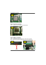
Step 2-3: Heat Sink Installation ...................................................................... 12
Step 2-4: Memory Installation ....................................................................... 12
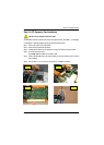
Step 2-5: PCI Expansion Card Installation ...................................................... 13
Step 2-6: Hard Disk Drive Installation ............................................................. 14
Step 2-7: FAN Duct Installation ..................................................................... 15
Step 2-8: Reinstall Top Cover ...................................................................... 15
Chapter 3 Appearance of GS-SR125EDL .........................................16
3-1: Front View of GS-SR125EDL ................................................................. 16
3-2: Rear View of GS-SR125EDL ................................................................. 17
3-3: IDE Backplane Layout and Description ................................................... 18
3-4: Switch and LED Indicators Description ..................................................... 19
3-5: HDD LED Indicators Description .............................................................. 20
3-6 : Connector Icon Description ................................................................... 21
Chapter 4 Motherboard Layout & Jumper Setting Introduction ...........22
GA-8EGPDRE Motherboard Layout ...............................................................22
GA-8EGPDRE Motherboard Layout Description .........................................23
Chapter 5 BIOS Setup ....................................................................33
Main .......................................................................................................................35
Advanced...............................................................................................................38
Advanced Processor Option ........................................................................ 39
PCI Configuration ....................................................................................... 40