


11
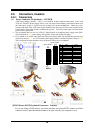
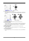
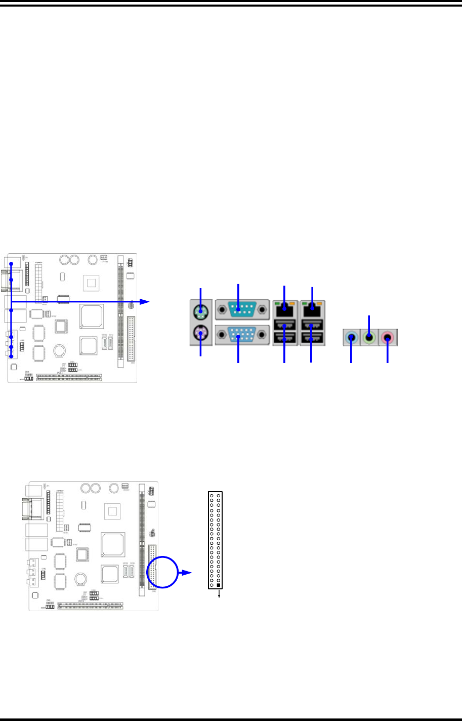
(3) USB Port connector: UL1 / UL2
The connectors are 4-pins connector that connect USB devices to the system board,
and standard RJ45 connector for Gigabit or 10/100 BASE-T LAN function.
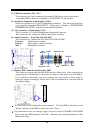
(4) Serial Port Connector (9-pin female): COM1
Serial Port connector is a 9-pin D-Subminiature connector. The On-board Serial Port
can be disabled through the BIOS SETUP. Please refer to Chapter 3 “INTEGRATED
PERIPHERALS SETUP” section for more detail information.
(5) VGA Connector (15-pin female): VGA
VGA
Connector is a 15-pin D-Subminiature Receptacle connector.
This connector is for connection Monitor and System to display.
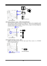
(6) Audio Connector: (Line-Out/ Line-IN/ MIC)
This Connector are 3 phone Jack for LINE-OUT/ LINE-IN/ MIC.
Line-out :
Audio output to speaker
Line-In :
Audio input to Audio controller
MIC :
Microphone Connector
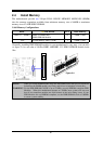
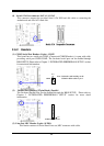
(7) Primary IDE Connector (40-pin block): IDE1
This connector supports the provided IDE hard disk ribbon cable. After connecting the
single plug end to motherboard, connect the two plugs at other end to your hard disk(s).
If you install two hard disks, you must configure the second drive to Slave mode by
setting its jumpers accordingly. Please refer to the documentation of your hard disk for
the jumper settings.
Pin 1
IDE1
•
Two hard disks can be connected to each connector. The first HDD is referred to as the
“Master” and the second HDD is referred to as the “Slave”.
•
For performance issues, we strongly suggest you don’t install a CD-ROM or DVD-ROM
drive on the same IDE channel as a hard disk. Otherwise, the system performance on this
channel may drop.
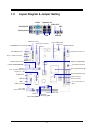
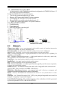
PS/2
MOUSE
PS/2
Keyboard
MIC LINE OUT
USB
VGA
LINE IN
COM1
Optional LAN