


13
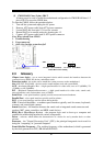
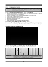
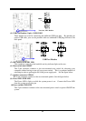
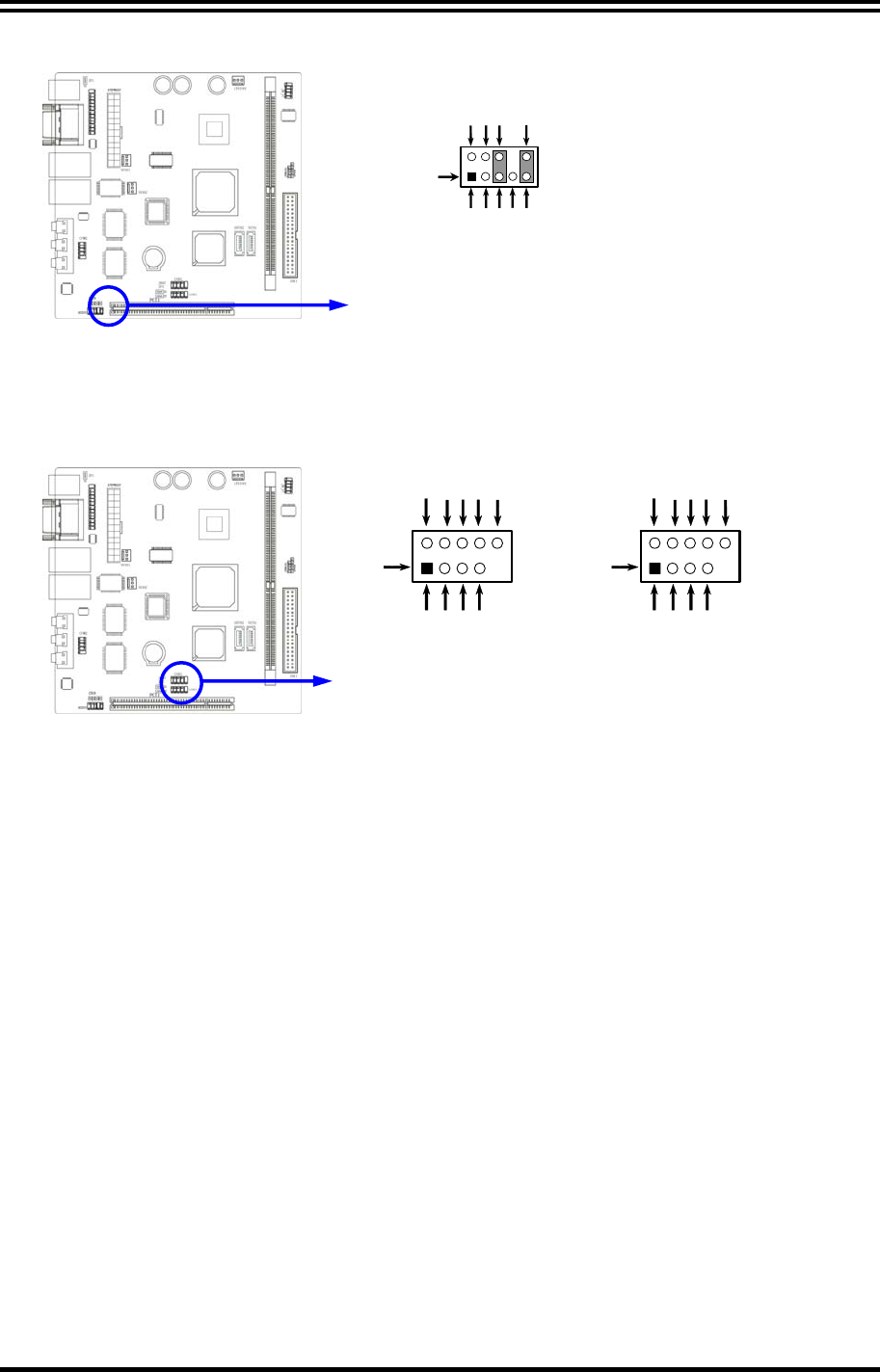
Line-Out, MIC Headers
AUDI O
Pin 1
AUD
-
MIC
AUD
-
FPOUT
-
L
AUD
-
MIC
-
BIAS
AUD
-
FPOUT
-
R
HP
-
ON
AUD
-
GND
AUD
-
RET
-
L
AUD
-
RET
-
R
AUD
-
V CC
2
9
10
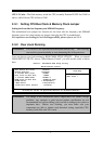
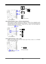
(4) USB Port Headers (9-pin) : USB1/USB2
These headers are used for connecting the additional USB port plug. By attaching an
option USB cable, your can be provided with two additional USB plugs affixed to the
back panel.
USB Port Headers
Pin 1
USB1
VCC
-DATA
GND
+DATA
VCC
OC
-DATA
GND
+DATA
Pin 1
USB2
VCC
-DATA
GND
+DATA
VCC
OC
-DATA
GND
+DATA
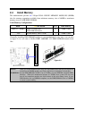
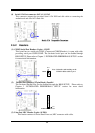
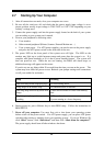
(5) IDE Activity LED: HD_LED
This connector connects to the hard disk activity indicator light on the case.
(6) Reset switch lead: RESET
This 2-pin connector connects to the case-mounted reset switch for rebooting your
computer without having to turn off your power switch. This is a preferred method of
rebooting in order to prolong the lift of the power supply unit. See the figure below.
(7) Speaker connector: SPEAK
This 4-pin connector connects to the case-mounted speaker. See the figure below.
(8) Power LED: PWR LED
The Power LED is light on while the system power is on. Connect the Power LED
from the system case to this pin.
(9) Power switch: PWR BTN
This 2-pin connector connects to the case-mounted power switch to power ON/OFF the
system.