


Installation
2 3A1931A
Installation
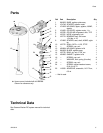
Remove Agitator 1.5.5B
1. Perform the Shutdown and Pressure Relief Proce-
dures in the Gusmer-Decker RC system manual.
2. Disconnect incoming power from agitator motor.
3. Disconnect all air lines from lid.
NOTE: The tank lid and agitator assembly weighs
approximately 100 lb (45 kg).
4. Loosen tank lid clamps then remove tank lid and
agitator assembly from tank.
5. Remove two hex head cap screws (A10) then
remove agitator shaft (A11) from agitator
housing (A07).
6. Remove lube cup and fittings assembly (A08) from
the agitator housing (A07).
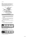
NOTE: Before performing the following step, use a small
piece of masking tape to note the location of the motor
relative to the tank lid. This will ensure the motor (A13)
is re-installed in the proper orientation.
7. Remove four screws (A12) then remove agitator
motor (A13) from gear reducer (A01).
8. Remove four screws and washers (A05) then
remove gear reducer (A01) from base (A04).
9. Loosen coupling set screw then remove
coupling (A02) from gear reducer.
10. Remove two hex head cap screws (A03) then
remove base (A04) from agitator housing (A07).
11. Remove four socket head cap screws (A06) then
remove agitator housing (A07) and seal (A09) from
tank lid.
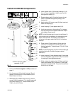
NOTE: Prior to beginning the Install Kit 24K408 Com-
ponents procedure, discard or set aside all items
except those noted in FIG. 1. This will prevent confusing
parts from 1.5.5B with parts from 24K408.
FIG.1
A10
A11
A08
A06
A05◆
A03
A02
A04
From Tank
Assembly◆
A01◆
A07
A09
ti17567a
A12◆
A13◆
◆ Items are needed during 24K408 installation.
All other items can be discarded.
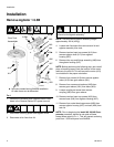
To prevent injury, use proper lifting equipment to raise
the tank lid and agitator assembly.