


Installation
3A1931A 3
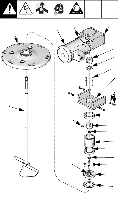
Install Kit 24K408 Components
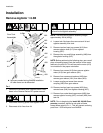
1. Perform the Remove Agitator 1.5.5B procedure on
page 2.
2. Use four screws (16) to install housing (12) and
gasket (15) onto tank lid. Torque screws (16) to
30-45 ft-lb (41-61 N•m).
3. With spacer (9) installed over seal (10), use four
screws (18) and washers (17) to install housing (4)
onto other housing (12). Torque screws (18) to
75-80 in-lb (8.5-9.0 N•m).
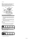
4. Insert agitator shaft (13) through housings (4, 12)
then use snap ring pliers to install snap ring (14)
onto groove in shaft (13).
5. Rotate agitator shaft (13) so that flat spot for set
screw is viewable through the opening in the
housing (4).
6. Apply sealant (25) to set screw (24) then insert set
screw into coupling (7).
7. Install coupling (7) onto agitator shaft (13).
8. Verify the set screw in the coupling (7) is located
over the flat spot on the agitator shaft then tempo-
rarily tighten the set screw.
NOTE: In the following step, be sure to install base (1)
so that motor can be installed in the orientation noted
when it was removed. The opening in the base is
off-center so the gear reducer will only fit in the base
one way.
9. Place spacer (3) onto housing (4) then use four
screws (11) to install base (1) onto spacer and
housing assembly. Torque screws (11) to 8-12 ft-lb
(11-16 N•m).
NOTE: In the following step, the face of the coupling (5)
should be flush with the end of the gear reducer
shaft (A01).
10. Install coupling (5) and alignment disk (6) onto gear
reducer shaft (A01). Apply sealant (25) to set screw
in coupling (5) then tighten set screw.
11. While rotating the agitator shaft (13) back and forth,
insert gear reducer (A01) into base (1) then install
screws and washers (A05). Torque screws (A05) to
30-45 ft-lb (41-61 N•m).
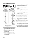
FIG.2
From Tank
Assembly
13
15
12
16
4
9
17, 18
7
6
5
3
1
11
24
14
ti17568a
10
◆ Items are from agitator
assembly 1.5.5B.
A01◆
A05◆
A13◆
A12◆