


Installation
4 3A1931A
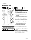
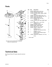
NOTE: In the following step, the agitator shaft must be
rotated by turning the gear reducer input sleeve
shaft (A01a). Attempting to rotate the agitator shaft by
rotating the agitator shaft itself will not work. This is due
to the design of the gear reducer. See FIG.3.
12. Rotate the gear reducer input sleeve shaft (A01a) to
turn the agitator shaft so that the set screw (24) in
the coupling (7) is visible through the opening in the
housing (4).
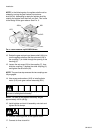
13. Loosen the set screw (24) in the coupling (7), then
slide the coupling (7) against the other coupling (5)
and tighten the set screw (24).
NOTE: The previous step ensures the two couplings are
fully engaged.
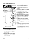
14. Use screws and washers (A12) to install agitator
motor (A13) onto gear reducer assembly (A01).
NOTE: The tank lid and agitator assembly weighs
approximately 100 lb (45 kg).
15. Install agitator and tank lid assembly onto tank and
tighten the lid clamps.
16. Connect incoming power to the agitator motor.
17. Connect air lines to tank lid.
FIG. 3: Gear Reducer Input Sleeve Shaft
To prevent injury, use proper lifting equipment to raise
the tank lid and agitator assembly.
A01a
ti17566a
A01
A13
A12