


Installation
8 333492B
Installation
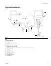
NOTE: The letters used in the following instructions
refer to Typical Installation on page 7.
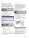
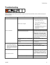
Pressure Relief Procedure
Follow the Pressure Relief Procedure whenever
you see this symbol.
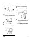
1. Turn off power supply to the pump or close
upstream master air valve (E).
2. Open all fluid shut off valves (J and L) in the system.
3. Trigger the meter (N) into a waste container to
relieve pressure.
4. Open fluid drain valves and leave them open until
you are ready to pressurize the system.
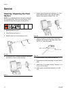
Grounding
Ground all components in the system:
Pump (F): Follow manufacturer’s recommendations.
Air and fluid supply lines (A, B, K): Only use electri-
cally conductive hoses. Check electrical resistance of
hoses. If total resistance to ground exceeds 29 meg-
ohms, replace hose immediately.
Air compressor: Follow manufacturer’s recommenda-
tions.
Fluid supply container: Follow local code.
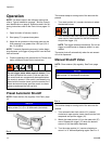
To maintain grounding continuity when flushing or
relieving pressure: hold a metal part of the meter firmly
to the side of a grounded metal pail, then trigger the
valve.
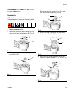
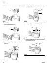
SDMM8 and SDMP8 Meter (N): When installing the
meter leave at least two threads bare when using thread
sealant. The bare threads ensure a ground is main-
tained.
This equipment stays pressurized until pressure is
manually relieved. To help prevent serious injury from
pressurized fluid, such as skin injection, splashing
fluid and moving parts, follow the Pressure Relief
Procedure when you stop spraying and before
cleaning, checking, or servicing the equipment.
• The equipment must be grounded to reduce the
risk of static sparking. Static sparking can cause
fumes to ignite or explode. Grounding provides
an escape wire for the electric current.
• To prevent electric arcing do not allow the
conductive metal surfaces on the meter to make
contact with any positively charged metal
surface, including (but not limited to), the starter
solenoid terminal, alternator terminal or battery
terminal.