


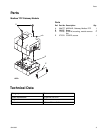

Overview
4 334183A
Overview
Module Description
The Modbus TCP (MBTCP) Gateway Module provides a
control link between a Modbus TCP fieldbus and a sys-
tem that uses Graco Control Architecture (GCA). This
link provides the means for remote monitoring and con-
trol by an external automation system.
Data provided by the MBTCP Gateway Module to the
fieldbus depends on the GCA-based system. Mapping
of Modbus registers is loaded by the host GCA system
and varies by system.
Data Exchange
Data is available by block transfer or by explicit access
to individual attributes as defined by the fieldbus specifi-
cation.
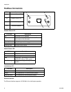
Module Status LED Signals
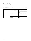
NOTE:
If you get a “No Valid Map” error, disable and re-enable
your gateway from the host device.
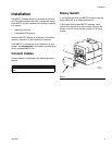
Module Requirements
Power Supply
The MBTCP Gateway Module requires a 12-30 VDC @
0.2 A power supply. Refer to the system manual for sys-
tem level power supply guidelines.
Environment Conditions
Refer to the system manual for guidelines regarding
environment conditions for the MBTCP module.
Signal Description
Green on The system is powered up.
Yellow Internal communication is in prog-
ress.
Red
Solid
MBTCP hardware failure
Red Flashing The red LED (F) will flash a code,
pause, then repeat. See MBTCP
Module Errors on page 7 for
details.
3 flashes The host device of the mapped
property is not responding.
4 flashes No valid mapping is set by the
host.
5 flashes MBTCP is not connected or the
system has an invalid network
configuration.